Portfolio
Hello. I am
a Mechatronic
Engineering Student
based in Cheltenham.
Inspired by the curiosity for math and physics I have had since before university, I enjoy engineering because of its challenges and logical processes. One of my strongest areas within the engineering field is programming. I have picked up a range of programming languages including:
- Python
- Arduino (C++)
- Visual Studio
- HTML and CSS
This allows me to program from website frontends to robotic controllers and data analysis applications. My hobby for programming was a key factor in my decision to study Mechatronics engineering. Recently, I have developed a strong set of CAD skills and am fascinated by design and innovation.
I grew up in a British family living in Mexico. Being embedded in the Mexican culture while maintaining our international roots at home has made me fluent in both English and Spanish. I have benefitted from the experience and connection to both countries in multiple ways:
- I am easily adaptable
- I can look at situations from multiple cultural perspectives
- I am empathetic with people from various cultures and backgrounds
I have visited other countries including the U.S. and Canada and enjoy meeting new people and understanding different lifestyles. Overall, I regard social and communicative skills as a very important part of a person's skillset.
- Knowledge, Skills and Behaviours
SolidWorks CAD
Prototyping Materials
3D Printing
DC Motors
Gearing Systems
Engineering Mathematics
Dimensioning
CAD Modeling
Design for X
Defining Specifications
Design within resources and budgets
Project Management
Clear Communication
Leadership
Logical Problem Solving
Team Player
- Project Objectives
As a university project for my Systems Design module, this was a team project where we were provided a set of specifications to build an interior pipe climber. Using these specifications and any others that surfaced from the design process, the challenge was to design and prototype a pipe climber to test at the end of the semester. The submission needed to include an A1 poster providing our design details; a digital pack of 3D files, 2D drawings, and BOM; and a presentation with a scrutineering process.
- Identified Specifications and Requirements
The following are specifications directly from the project brief and others deduced from needs and ideal goals for the project outcome. They are split into constraints (strict requirements) and criteria (flexible necessities or goals).
Constraints:
- Dimensions of the PVC pipe
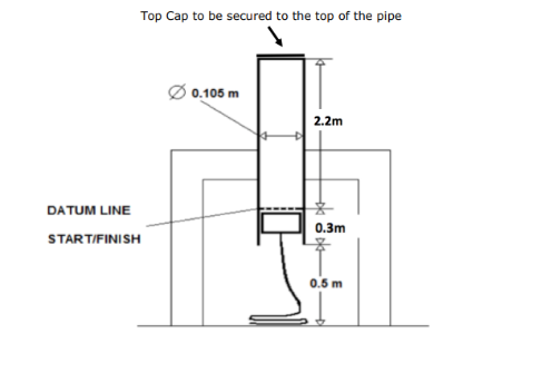
Pipe Dimensions - Powered with a motor of maximum 2W and 6V
- Maximum cost of prototype of £25
- Climb from inside the pipe
- Touch the top cap of the pipe
- Descend the pipe
- Carry a chain of 0.265kg weight and 2.5m length
- Maximum climber height of 0.3m (excluding a start switch) and width of 0.7056m diameter of the pipe
- Be self-contained
- DC power operated
- Not run on a programmable control unit
- Safe to run (no risk of entanglement, entrapment, or unsafe for users or spectators)
- Must run 3 laps per heat round (total of 6)
- Finish a lap of the pipe faster than 2 minutes
Criteria:
- Be able to climb the pipe within 30 seconds
- Hold itself within the pipe before running
- Not fall out of the bottom of the pipe
- Be light (weight defined by research into components)
- Not need any maintenance between running sets (does not exclude the development of spare parts)
- Light weight energy source
- Dimensions of the PVC pipe
- Design Proposal
After creating a Gantt chat with a scheduled layout of our time and development using the double diamond design process, the core functions (second and third images shown below) for the operation were defined and agreed upon.
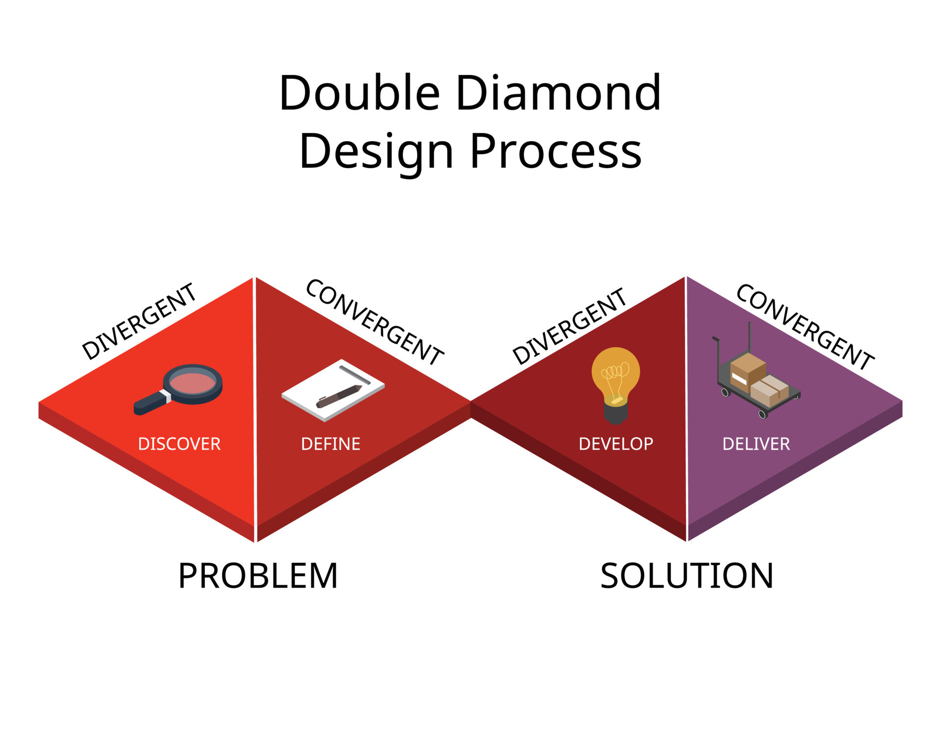
Double Diamond design process used for project planning 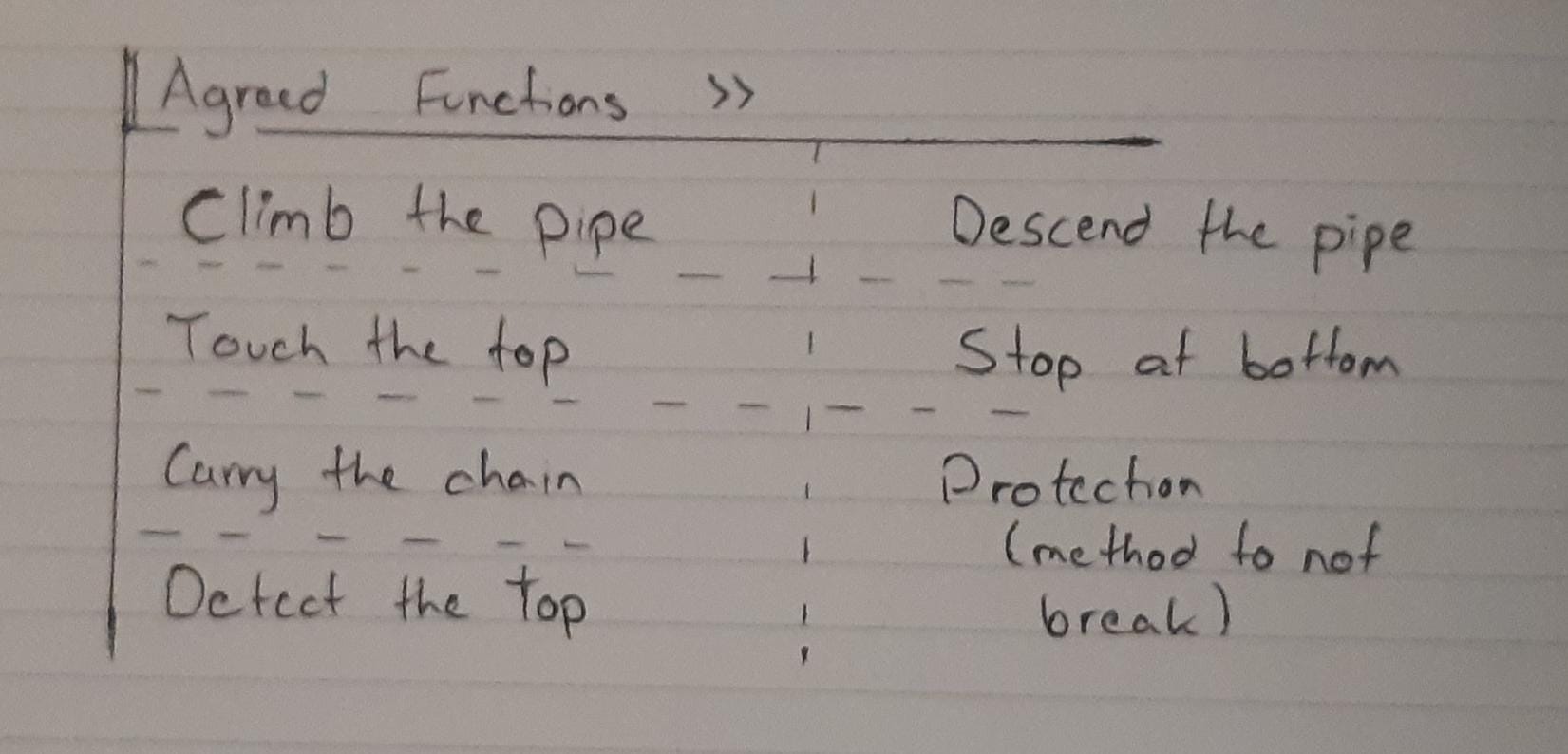
Agreed Functions 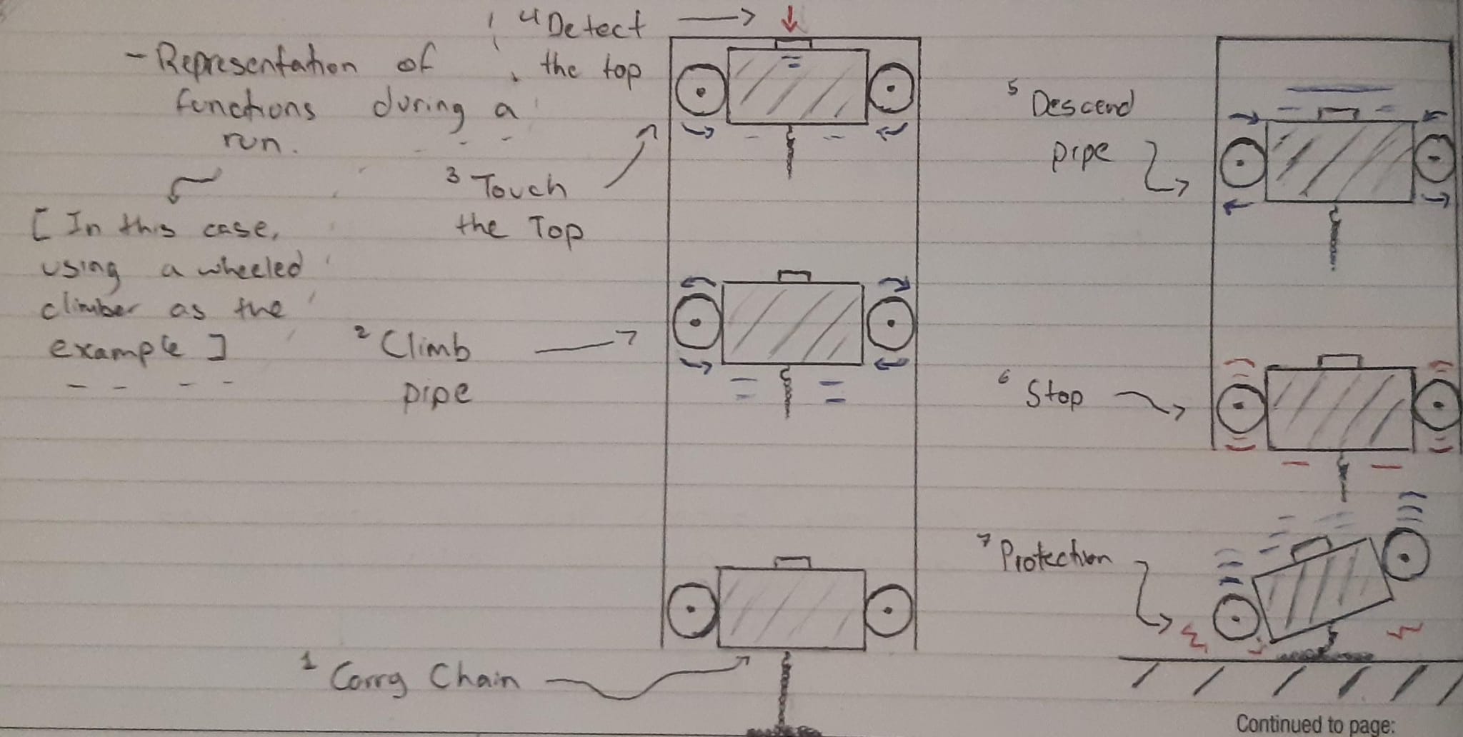
Representation of the Functions After developing a QFD (Quality Function Deployment) Matrix of solutions through a brainstorming process, there was a wide range of possible solution paths for the functions. A number of these solutions were discarded based on the requirements and the remaining were done through P-Matrices which tested them against different weighted criteria.
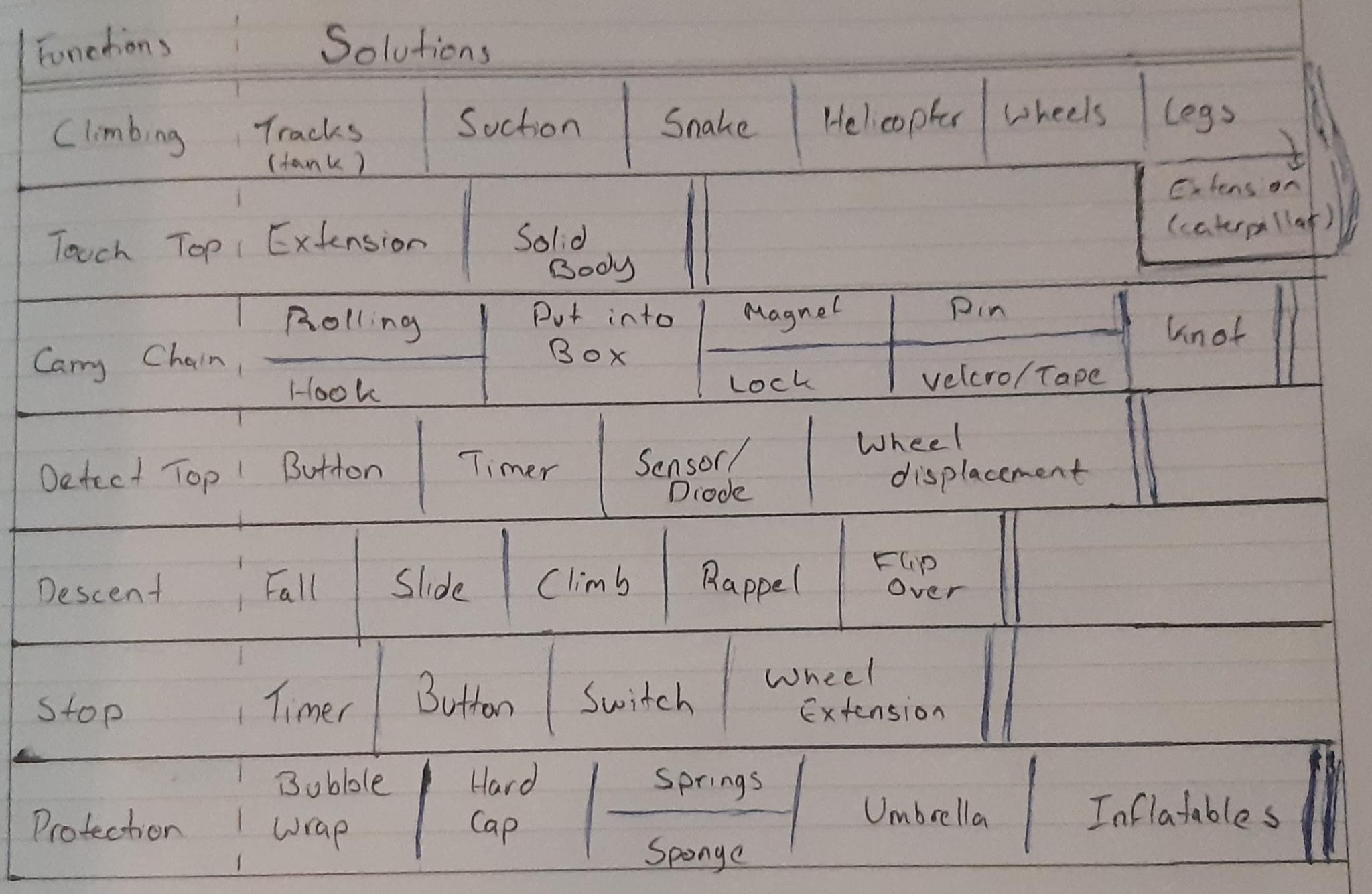
Quality Function Deployment 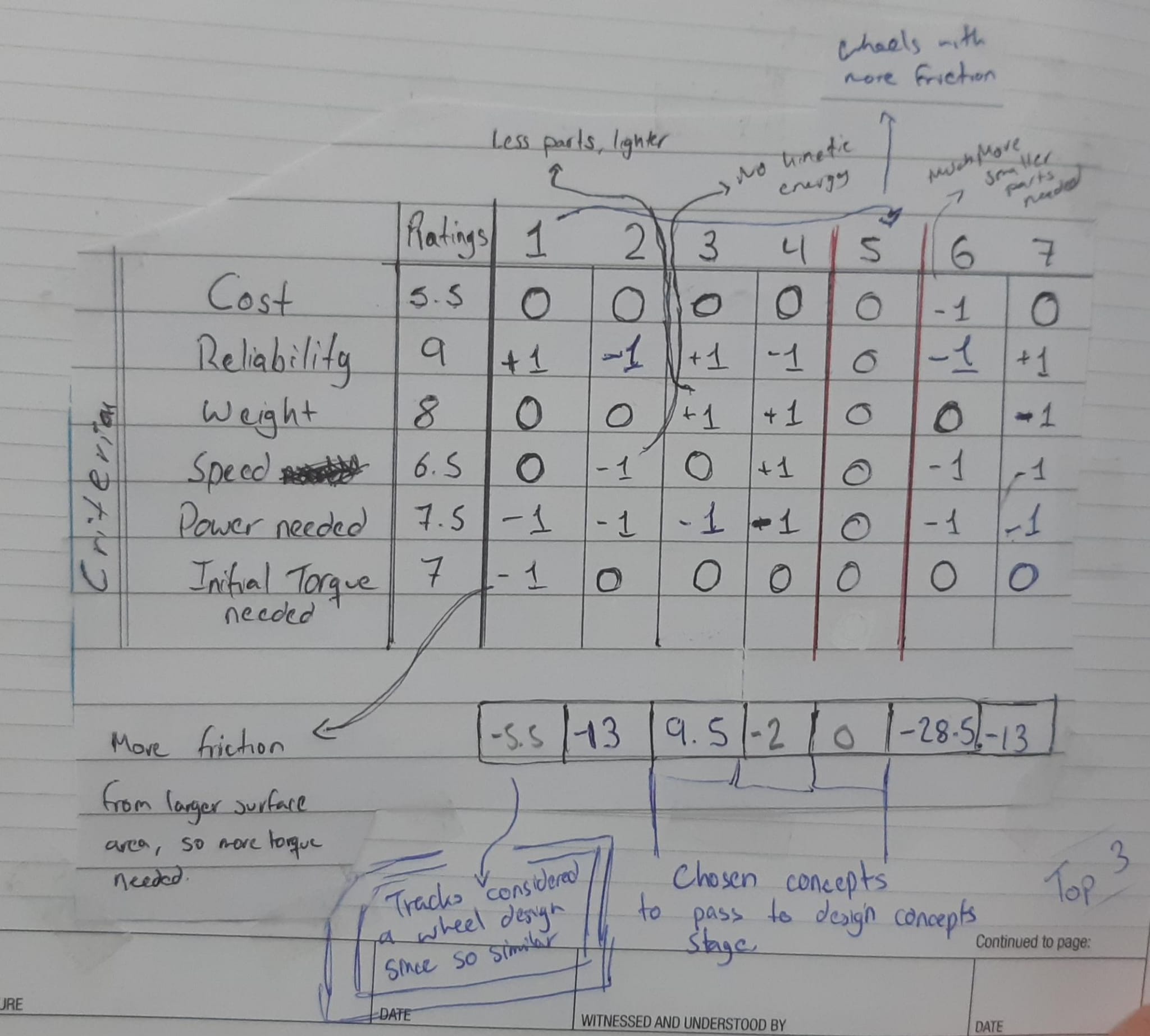
P-Matrix for the climbing function After these design decisions, I proposed a climber design using a set of tracks for ascending and descending, a hook to hold the chain, a set of friction brakes, a sponge base for protection, and a top button to switch the motor direction when touching the cap of the pipe. In addition to this, batteries and an initial motor were sourced, and the brake design was developed.
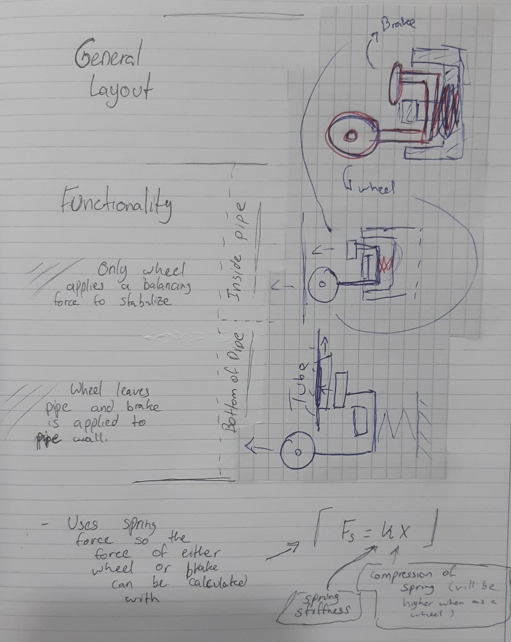
Brake Design 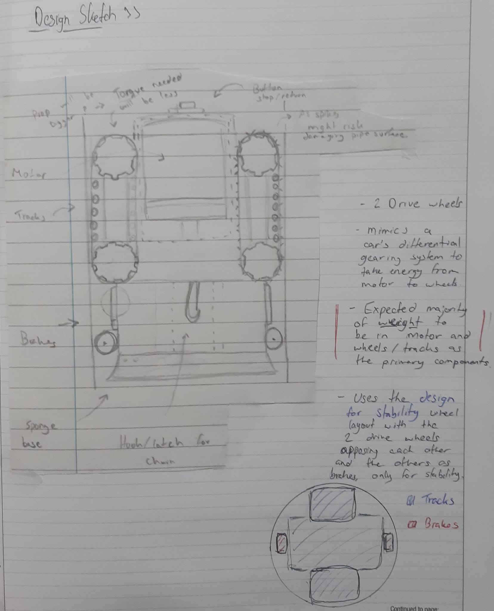
Pipe Climber Design The first motor for the pipe climber was chosen based on a fast rpm to quickly ascend and descend the pipe. Although this is ideal for the criteria in the specifications, fast rpm motors usually exchange speed for a lower torque. Torque is essential since it is needed for carrying the weight of the climber. A new high torque motor was chosen. The needed torque was measured based on an estimated mass of the system to be 583g or 5,719.23N and resulted in a torque of 3kg/cm. The final ordered motor was a 6V DC motor containing a 1:1000 reduction gearbox which allowed it to have a stall torque of 8kg/cm, making it great for the intended application. The only characteristic that could affect our outcome was its speed of 20rpm, which required covering the pipe within the time constraint.
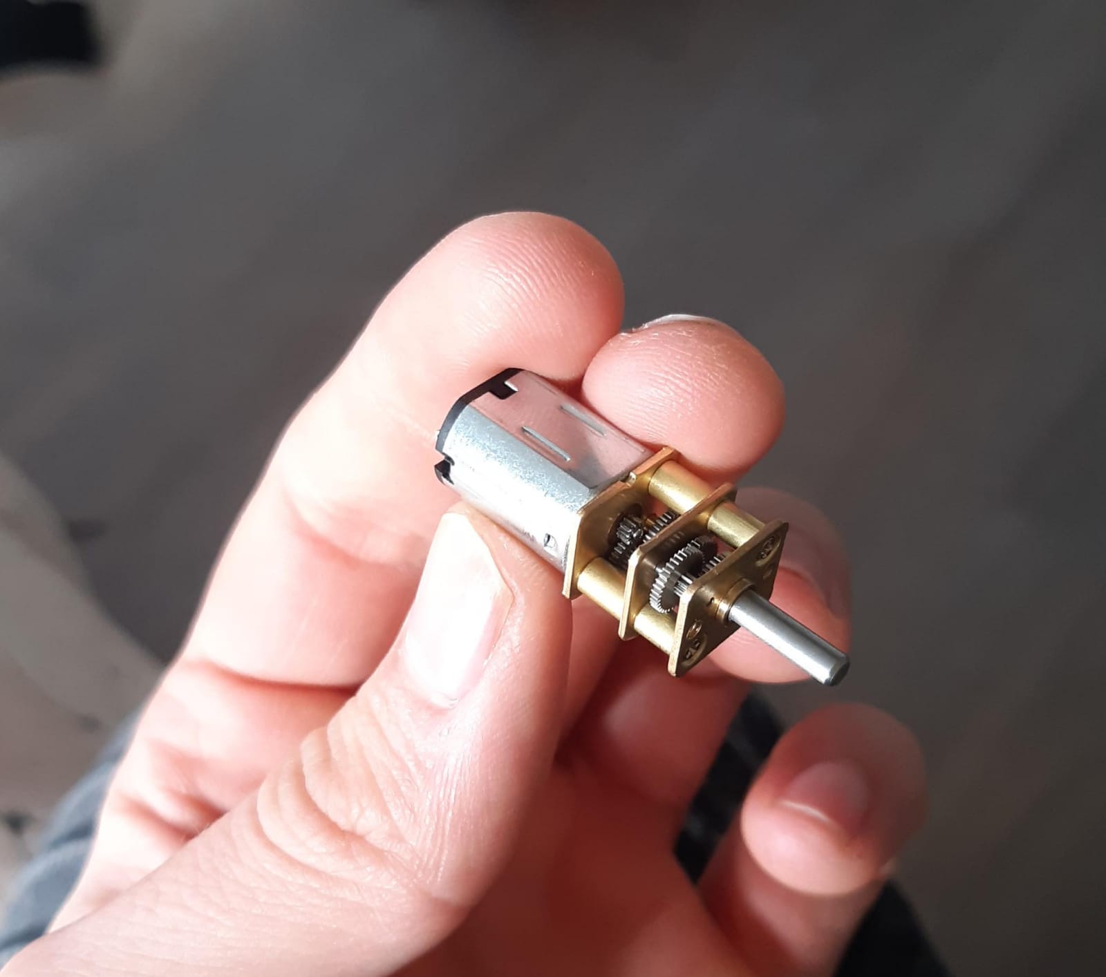
High torque motor chosen for the climber - Design: Track Wheel
One of the key designs that I did in this project was the design of the wheels to run the set of tracks. The climber design contained two tracks as seen in the design proposal section, some of the requirements the tracks needed were:
- They need a space between them where they can’t touch since they are moving parts
- They need to fit within the dimensions of the diameter of the pipe
- The wheels need bearings to run on static shafts to maintaining stability against the pipe wall
- The teeth of the wheels need to fit with the grooves on the sourced tracks
- Need to hold two tracks per side to make the most of the possible friction
- Need to have a radius that corresponds to the torque rating on the motor so that the climber can ascend
- Needed to rotate fast enough to cover the length of the pipe and back within the required time
The initial steps of preparing a prototype of the wheels consisted in theoretical estimations of the radius dimensions. The first version of the wheel used a Design for Speed approach. This considered that the larger the wheel, the more distance it would cover with 1 rotation since the circumference is the total displacement along the pipe. The mathematical model of the wheel was created based on a constant perimeter of 30cm (corresponding to the circumference of the track) and calculating the largest possible wheel. The image below shows this model.
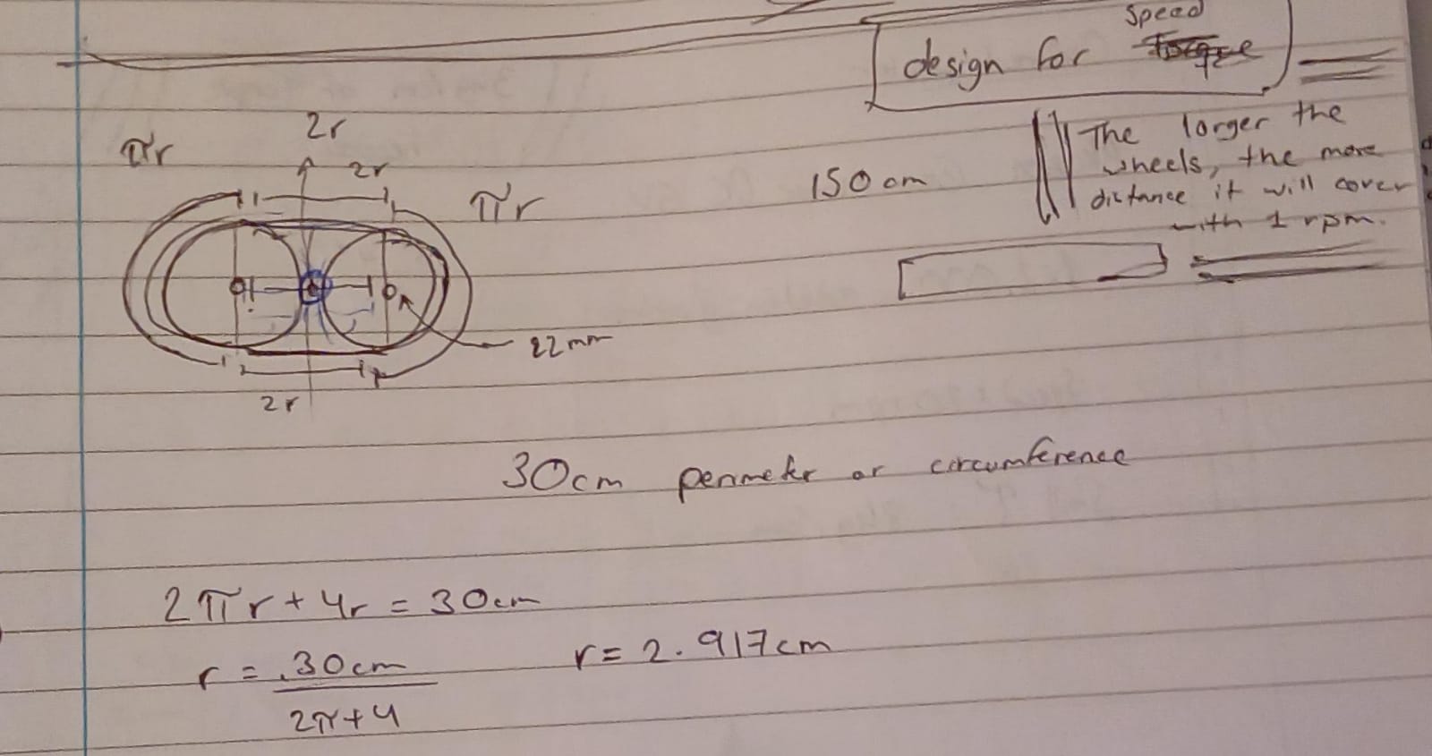
First mathematical approach to estimating the wheel dimensions Note that since wheels spin in the same direction, a space between the wheels needs to be added so that they don’t touch and cause friction when running. This space was initially planned to be occupied with a small gear which would provide some stability, but since the wheels are to be prototyped using 3D printing, this gear would need to be of a certain size to print, contradicting the aim of creating the largest possible wheels to run the tracks.
After sourcing the bearings, an initial version of the wheel was designed. It was created using a drawn design to attach two identical wheels together with 3 pegs, each with a section of the track. This meant that a total of 8 wheels would have been 3D printed if passed the testing phase.
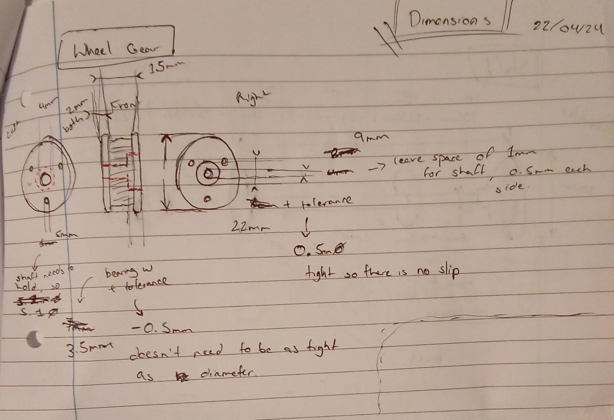
Design 2D dimensional drawing of the wheel with appropriate dimensions and details 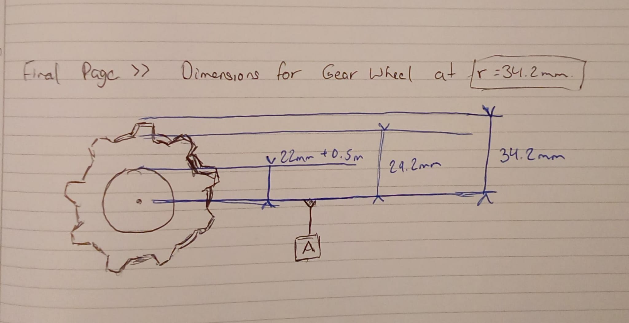
Mathematical model of estimated wheel radius size A shaft was also designed using a gearing system where a spur gear rotates the shaft which has bevel gears at the ends to transfer the energy to the wheels of the tracks (an initial dimension and design sketch I made is shown below). Finally, the first prototype of the wheel and the spur gear were printed in ABS.
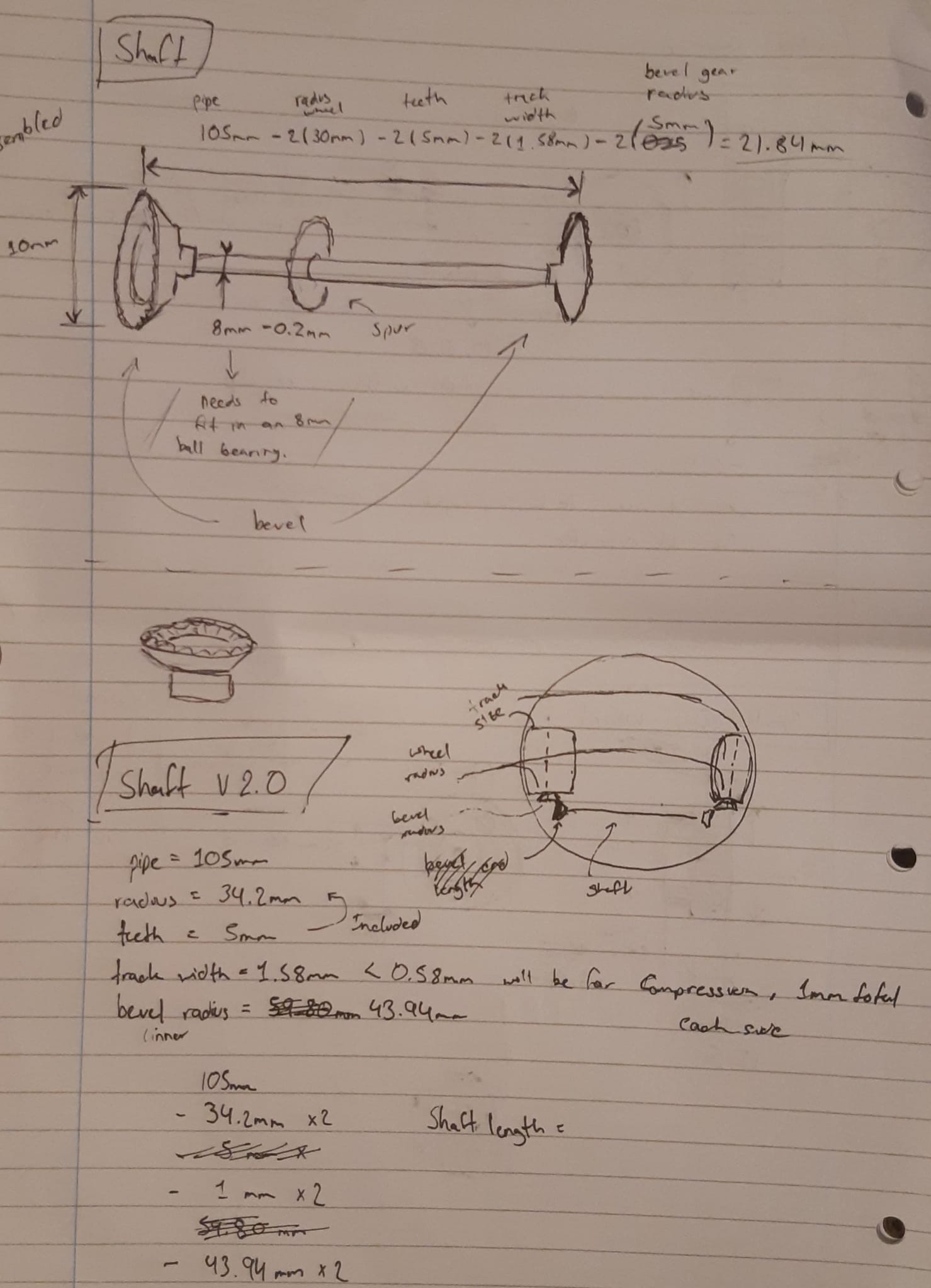
Shaft design sketch 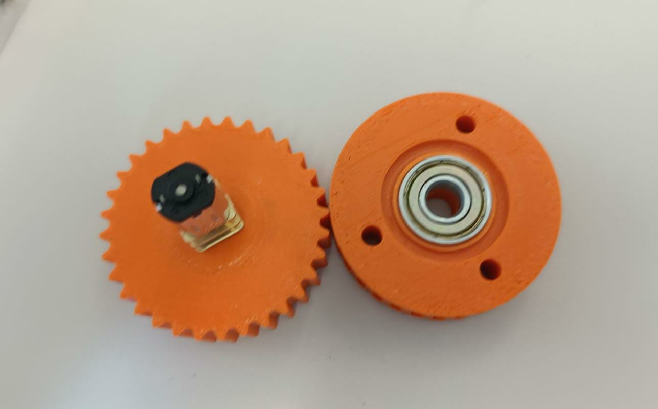
ABS 3D printed track wheel and spur gear - Testing and Further Prototyping
The first prototype of both the wheel and spur gear were tested and had some noticeable flaws including:
- Heavy weight which would affect our costs on the BOM (rapid prototyping was costed at 10p per gram regardless of the material)
- Incorrect spacing of teeth dimensions on the track wheel to hold the track
- Too large a radius on the wheels to fit the climber into the pipe (this was tested in the pipe itself)
As seen above in the image of both prototypes, some aspects that were working were:
- The bearing fit into the wheel with a tight interference fit, securing it in place
- The motor shaft fit well on the spur gear
The first change that was made to the models was the addition of spokes. These helped our Design for Weight, dramatically reducing the material cost while still maintaining strength against the stress forces applied by the tracks. Also, the holes and pins design for using two wheels together was passed as unnecessary and making the system more unstable. Instead of this, I modified the CAD design to be a single wheel holding both tracks. The barriers used to separate the tracks from overlapping was also given a 45° angle to provide simplicity for 3D printing, overhanging ledges at 0° (or printing an upside down L) would need supports between the teeth which would be a struggle to remove, designing for printing without supports is easier to accomplish.
The second versions of prototypes were printed in nylon which is stronger and less dense compared to ABS. Below are the range of component prototypes.

Prototyped track wheel with spokes for weight, track separators, and space for both tracks 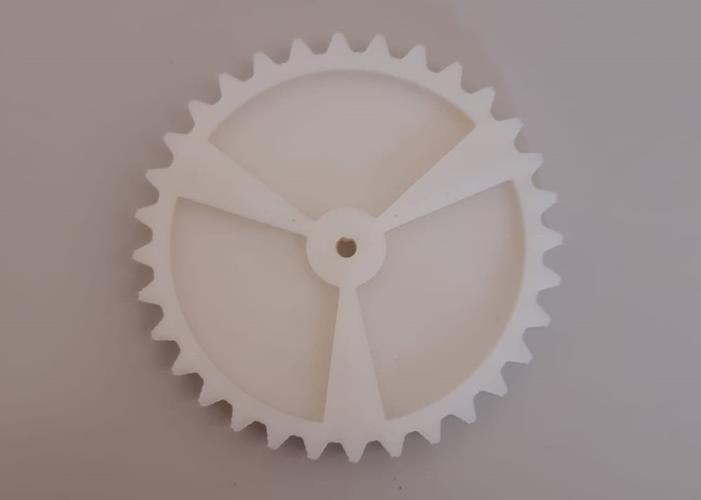
Prototyped spur gear with spokes and low thinkness for weight 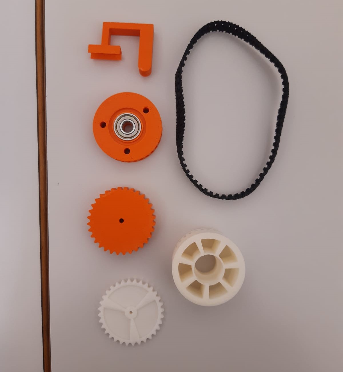
All current prototypes The second version of the track wheel prototype was tested with the tracks to observe if the teeth were the correct size. As shown below, the spacing between the teeth was still too low and would not be useful to run the tracks.
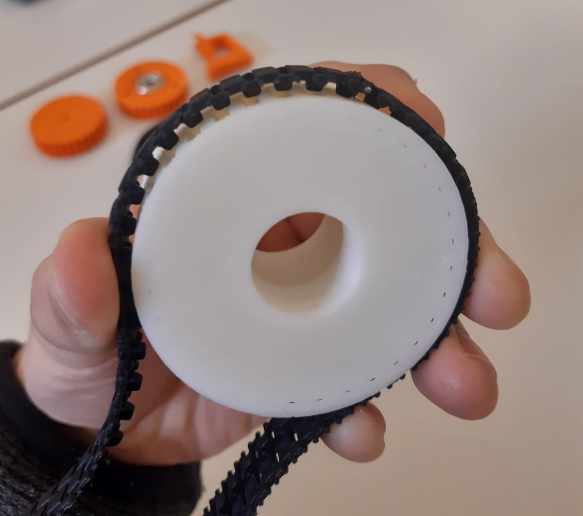
Testing of the teeth on the new prototyped version of the wheel For the final prototype of the track wheels, only the teeth were changed, they were modified to be further spaced out and with a sharper angle of inclination. This made them more triangular than square as they had been before. After this modification, the tracks fit with the teeth.
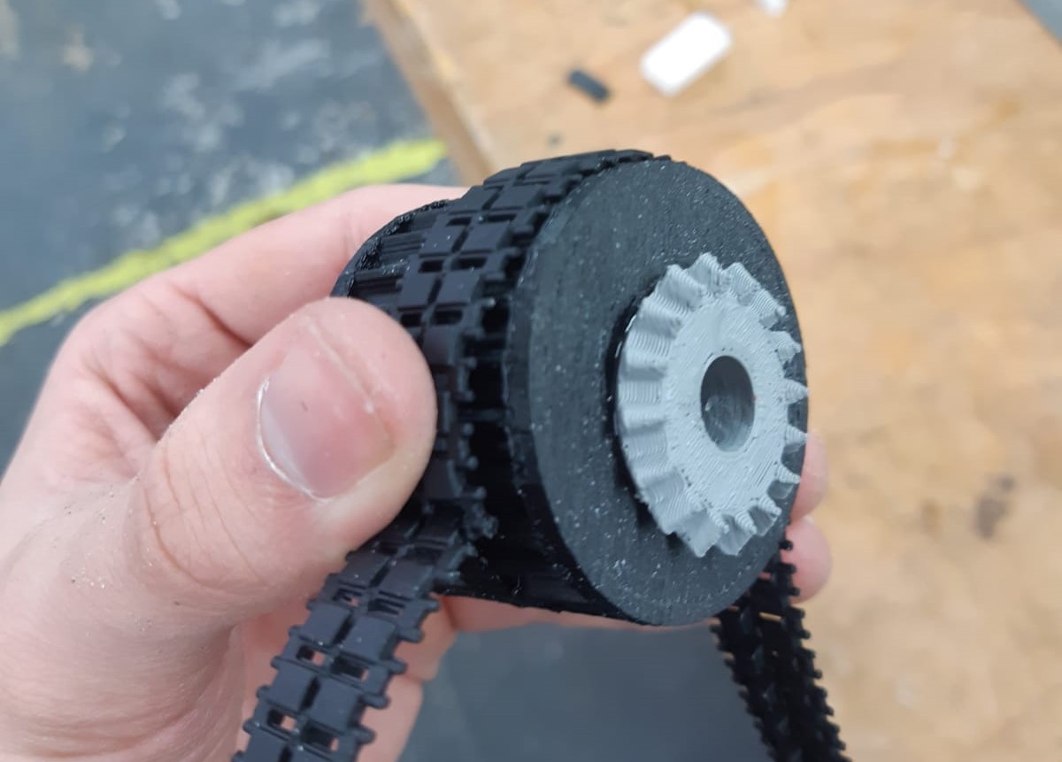
Final tested wheel prototype - Design: Chassis
-
Priority of Chassis
As a supportive component to hold the system together, the chassis must be tightly tolerances, and I had to consider the size of all other parts for its dimensions. I did the chassis creation since I had made the initial designs and dimensions for the wheels and gearing system.
-
Design
The design I created involved:
- Using two plates to hold the wheel shafts from each side
- Brakes in the middle of the body to not obstruct the gearing system running the top wheels. It was not placed at the bottom since most of this space was used by the bottom wheels
- Dimensions to fit accordingly into the pipe width and height requirements, including the held in the chassis
- Built in a triangular “x” form to direct forces from the wheels as tension trusses, designed for weight and robustness
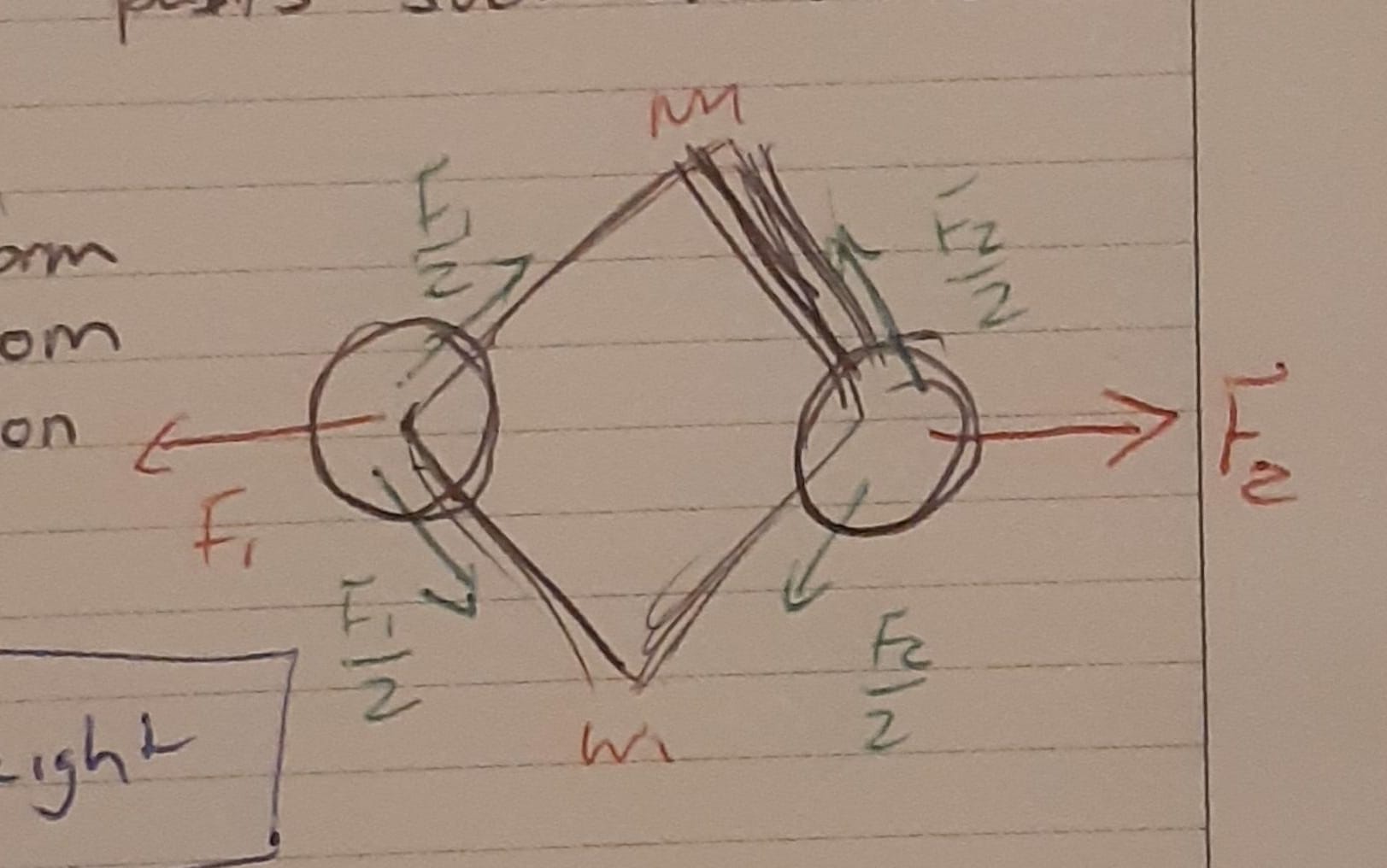
Chassis truss design - At the end of the designing process, each chassis side was split into 2 sections since it was too long to print in a single run, this meant it included a joint to strengthen the middle section of the chassis
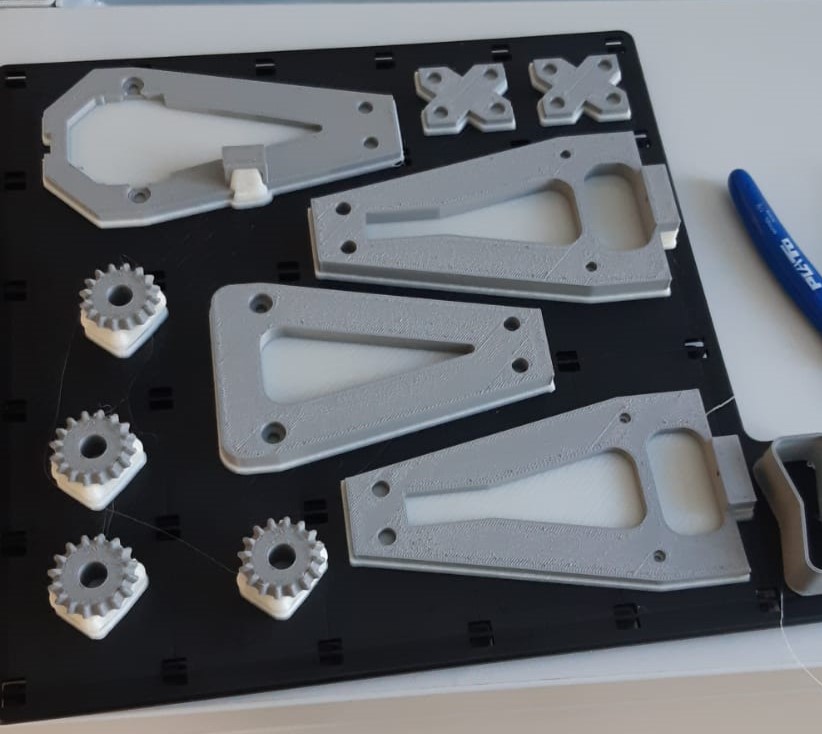
Prints of the chassis, joints, and bevel gears
The chassis took around 2 weeks to design. Since the dimensions of all the components needed to be considered, I found it easier to build the SolidWorks Assembly file parallel to the chassis 3D file. This functioned as a testing environment where I could be aware of necessary changes or errors in my design. A section of the pipe was also replicated in the CAD file to mimic the pipe dimensions and test if the construction would fit in the pipe.
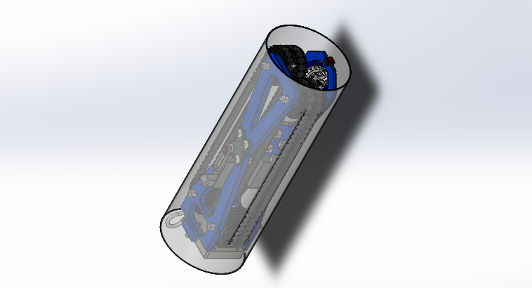
Pipe Climber CAD tested with a model of the pipe Unfortunately, since the chassis was one of the last part files to be designed, there was not sufficient time to test it as a prototype before the project hand-in, but the result was well dimensioned to hold most of the components and had a good fit in the pipe.
-
- Prototype
The final prototype was built for the final test in the pipe. Since we had been caught up on time after having spent many weeks on continuously prototyping components such as the wheels and brakes, we rushed to build a complete prototype for the project deadline. This prototype had great dimensioning for the pipe, but there were flaws in components which weren’t tested before. One of these was the hook which was only tested once prior to the final product. For the final test, the tracks weren’t added to the system because there weren’t enough of the final wheels printed on time. Instead of this, rubber bands were put on the wheels and demonstrated that, with tracks, the climber would fit and hold in the pipe.
Despite this, the models developed for prototyping and the overall design followed the specifications and requirements and proved to be a realistic solution if our time had been organized to leave space for testing the whole system in the final stages. Following is the final built prototype, some of the key components of the system, the CAD assembly, exploded drawing, and BOM.

Final built assembly of the pipe climber 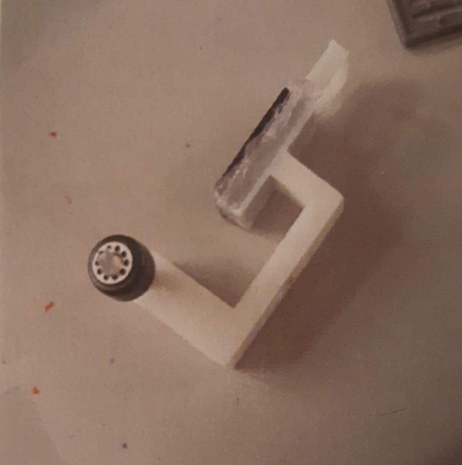
Final brake with rubber padding and guide wheel incorporated 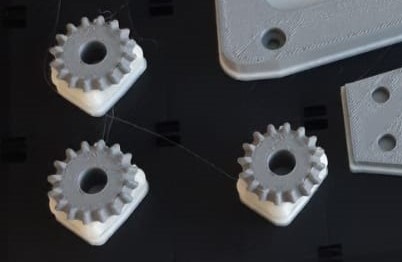
Final printed bevel gears used in tthe gearing system 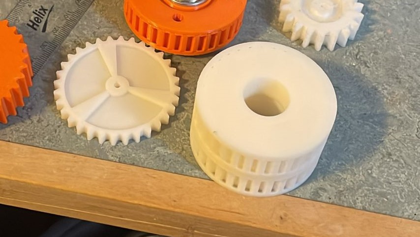
Wheel and spur gear of the final model 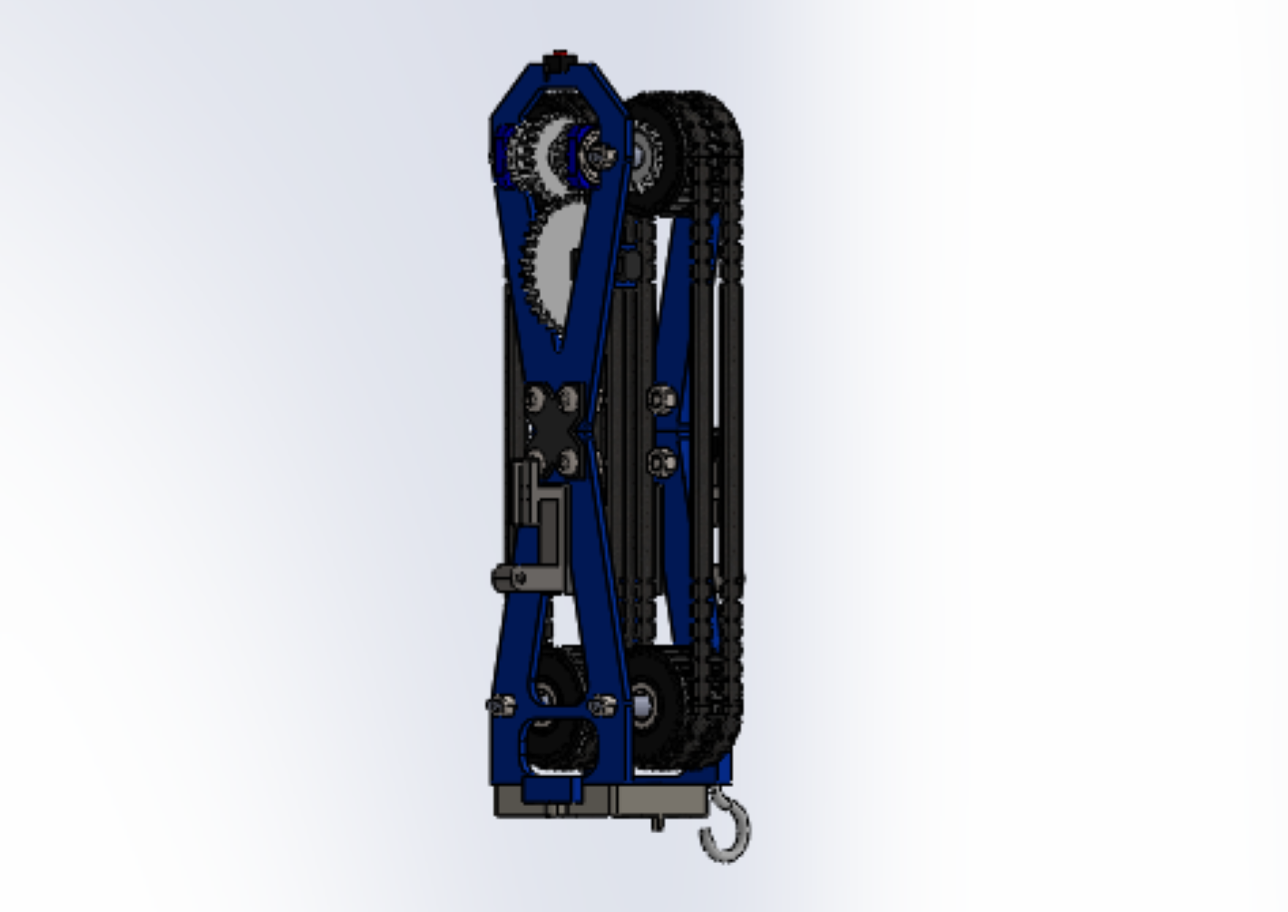
CAD file I built of the entire system 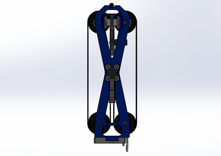
Front View 
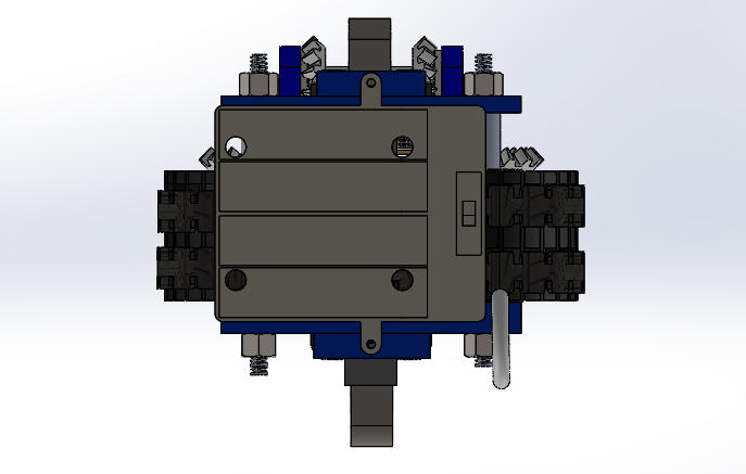
Top and bottom views 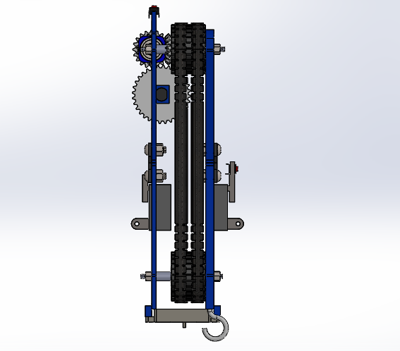
Side View 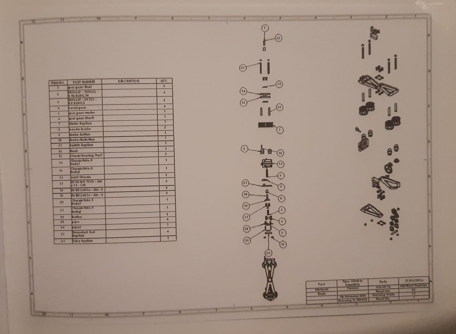
Exploded Drawing 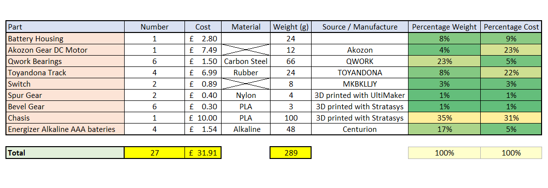
Bill of Materials, note that the chassis consumed a large amount of the bugdet (this was only printed once, if another prototype was made we could have easily solved this problem) - Conclusion and Reflection
What went well:
- Great concept design phase
- Functions correctly identified and concept developed according to fulfilling them.
- Many ideas searched and properly selected based on an objective screening process.
- Approach of finding a motor first had the benefit that we built and designed the system around sourced components.
- Mathematically, errors were noted and corrected, such as the motor specifications not having sufficient torque.
- Similarly, the result was backed well with theoretical functionality in mathematics.
- Designing parts individually helped clarify their functionality and assure their effectiveness.
- The assembly being developed parallel to the chassis made sure that all components were taken into consideration and that dimensions were accurate.
- Testing for parts allowed insight into bettering them such as with the gears and spokes for the weight of the system.
- Parts designed in a "design for X" format so that the requirements were taken into consideration while designing.
- Double diamond design process followed over the entire process.
What could be better:
- Not all team members worked equally. This meant that work was overloaded for a portion of the members.
- In addition to the above, since time was given for the members that did not finish work, designs and processes were backlogged from the original planning.
- Brainstorming was overly detailed into concepts and their alterations. Most of this information was not used so it ended up being a waste of meetings. I would have gone from here to concept screening if done again and the result would have saved weeks of work.
- Wheels were printed for the tracks; this design took time since the track had strict dimensioning. Especially for the teeth, which could change dimension as the track curves.
- Might have been better to change designs after errors of repeated complex dimensions.
- "Simplicity" should have been included in the criteria early in the process.
- Knowledge, Skills and Behaviours
Python
SQL Databases
GUI Development and Aesthetics
Object-oriented Programming
Flowcharts
Multiple File Programming
Debugging and Testing
Problem Solving
Logical Reasoning
Quality Focus
Resilience
- Project Objectives
In my first semester of university, I was tasked with using problem-solving and program system development taught in the module to construct a marketing application showing how different pieces of logic and Python can be linked to construct a single multifunctional task. This application had to be secure for users to access information about marketing promotions across different online sources using a clear and simple registration system to filter data precisely into a database, a simple GUI which allows users to clearly understand promotional information, and additional features to support finding information needed such as a search bar, categories, QR links to sources, and ratings to guide users about a product.
Based on this, my core objectives that I established for the project were:
- Clarity
- Visual Simplicity
- Efficient Filtering Systems
- System Design
-
Software Structure
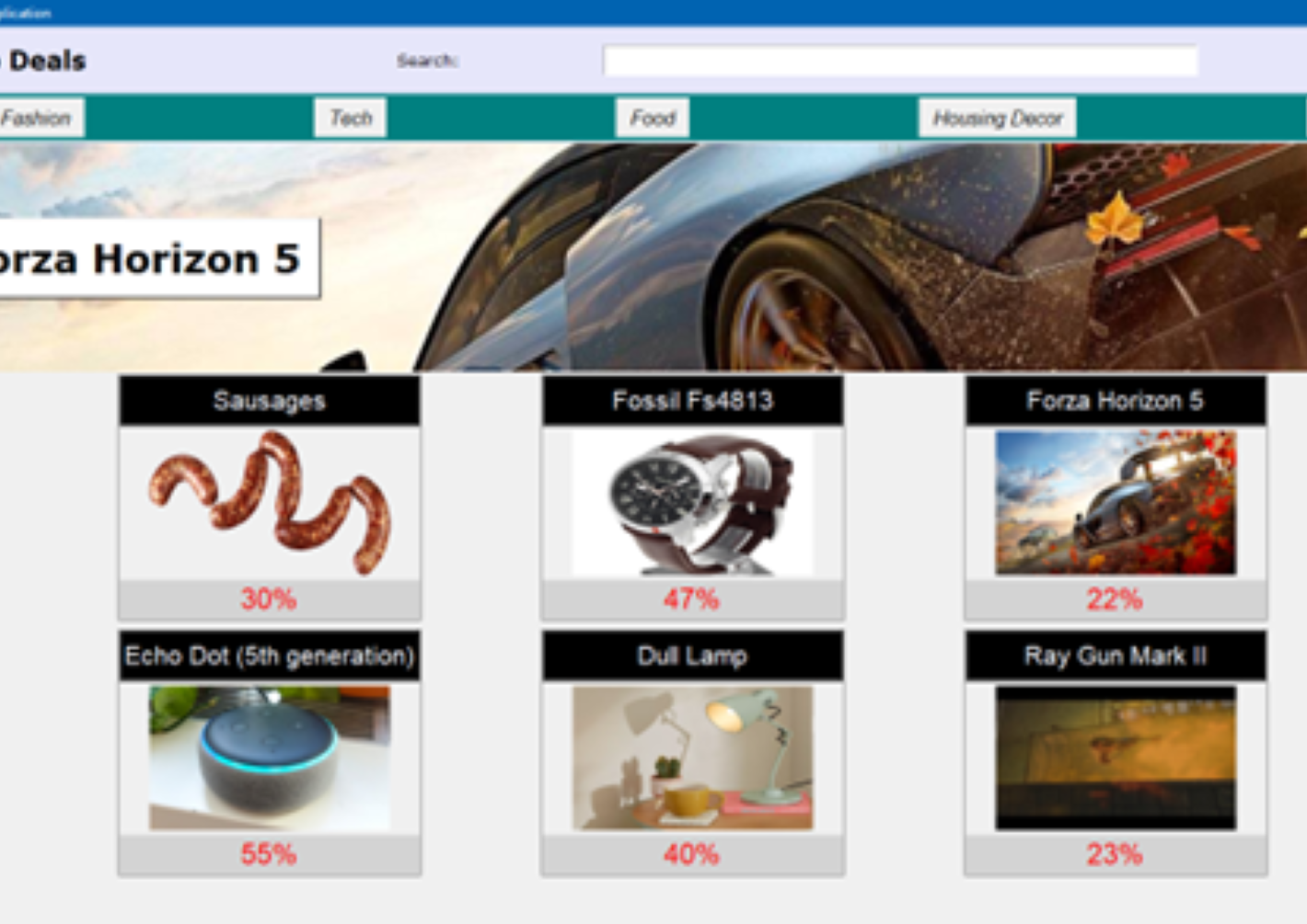
Instead of a single large file, the application revolved around a system of python documents that are all interlinked to the “main.py” file. This is a home page where users can ground themselves and spread out and back to the additional six GUI windows. Other than these files, there is a text file which saves the value of signed in user and the SQLite Database consisting of four tables: the users registered, the products, the categories, and ratings for products. They themselves are linked to each other by primary and foreign keys.

Imports of the multiple file system viewed from the "main.py" file Separation into files which call each other like module imports is an ideal way to organize blocks of code that perform tasks. Despite this, the way the developed program is separated based on GUI windows can also leave an unbalance in complexity of different files. Some of the windows such as the product window or the profile action windows can be straightforward because of their lack of multifunctionality within the page. On the other hand, a window like the main window has multiple complex features that work side by side on the page such as the search bar, the slider, and the category bar.
An alternate option to tackle this challenge would be to form an organization of different files with regards to functionalities in the application, compared to by graphics.
One of the main logical actions implemented into the software is the “signed_in.txt” file. Since creating a global “ID” variable that is functional, modifiable, and expansive over multiple interlinked files can result in a complex and confusing process when applied within the code, a resourceful solution is to rely on an external text file to save the variable data. This file can be interacted with freely either to read or modify whenever is needed and can allow the program to perform tasks such as creating a barrier on features when users are not signed in, accessing the ID of the user within different Windows of the application, and keeping the user account open even when the application is closed and reopened.
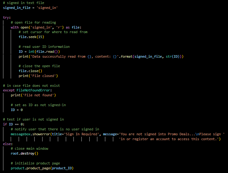
Initial code for the creation or reading of the global variable when a user opens the application 
View of the content of "signed_in.txt" in a notepad -
Program Features
The following are the main features of the program:
-
Register:
Requesting a user to input their Name, Email, Password, and Age to create an account for them in the Database, this process includes password hashing and attack preventions such as users under the age of 18 or the creation of accounts with repeated emails.
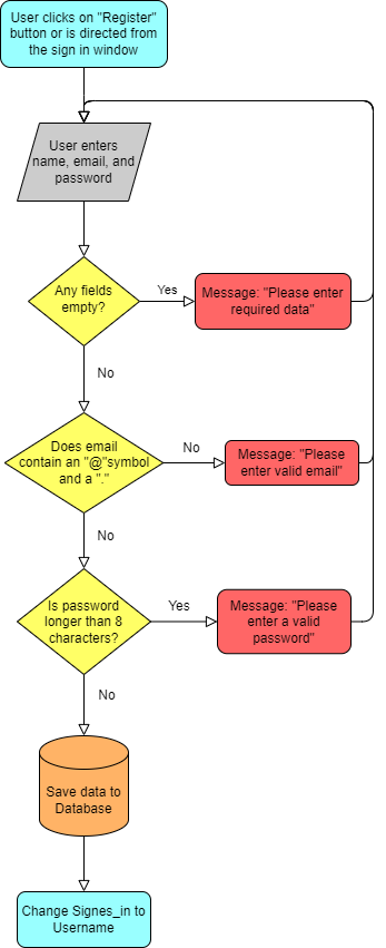
Logic map created prior to coding From designed, the test for real emails and password length were removed. In contrast, it included a test for if the email had already been registered on the Database, age attacks, and the creation of the user ID as one greater than the previous ID on the database or as “1” if currently none.
-
Sign In:
Considering a user’s data is already saved in the Database, they will only need their Email and Password to have full access to their account.
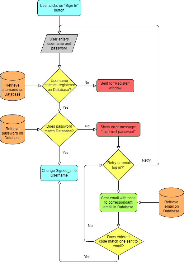
Logic map created prior to coding Changes contain the username in replaced with email, a test for empty entries, and the removal of the email option as it was not figured out.
-
Modify:
This window helps the user update their data that is stored in the Database.
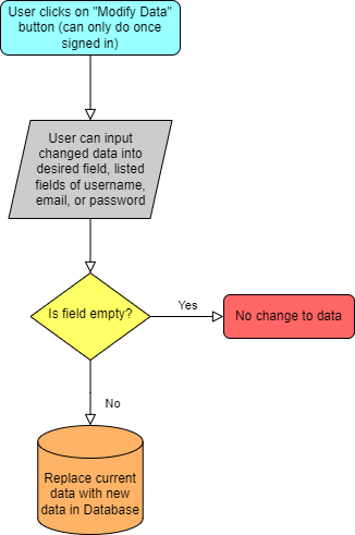
Logic map created prior to coding Apart from the data shown, a test for age attacks is included.
-
Main Window:
-
Search Bar:
For the user to rapidly locate a product or category, this feature helps guide users to their desired Window.
This feature tracks when a user types into an Entry section and searches the Categories and Products tables independently, comparing the items to the user’s query in order to match their search. If a result is clicked, the user will be relocated to the desired Product Window or Category Window.
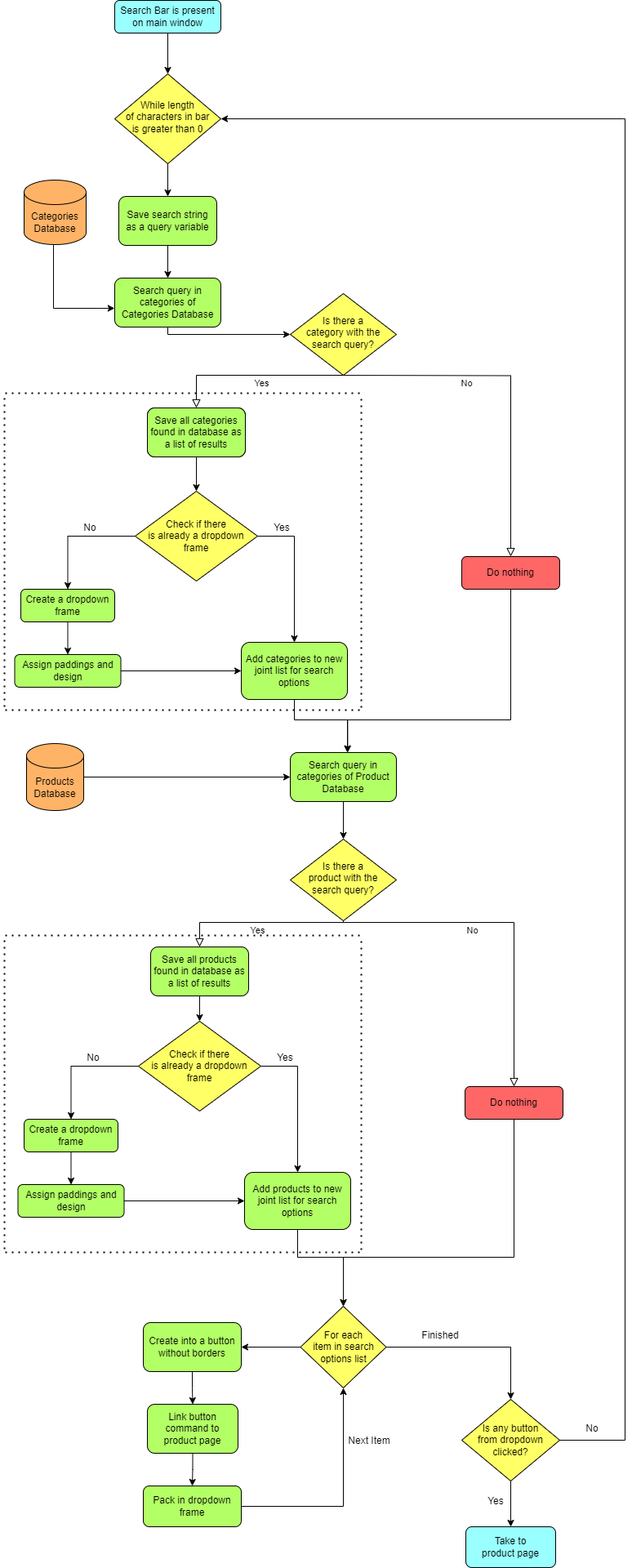
Logic map created prior to coding -
Category Bar:
The Category Bar has a button list of the categories in the Database which each lead to a Category Window showing a maximum of ten products belonging to this product genre.
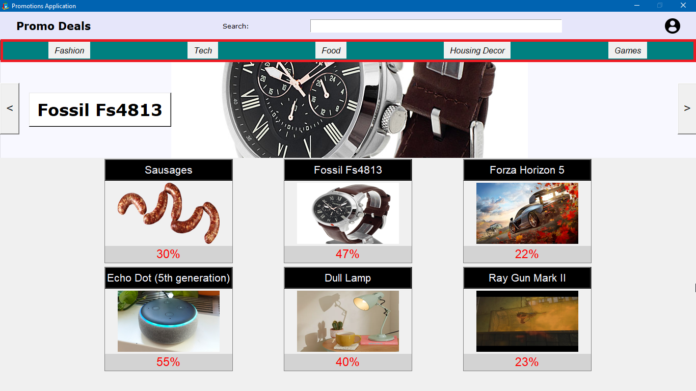
Category Bar located on app -
Slider:
Provides a rotating display of the top three averaged highest rated products in the Database and leads to their Product Pages.
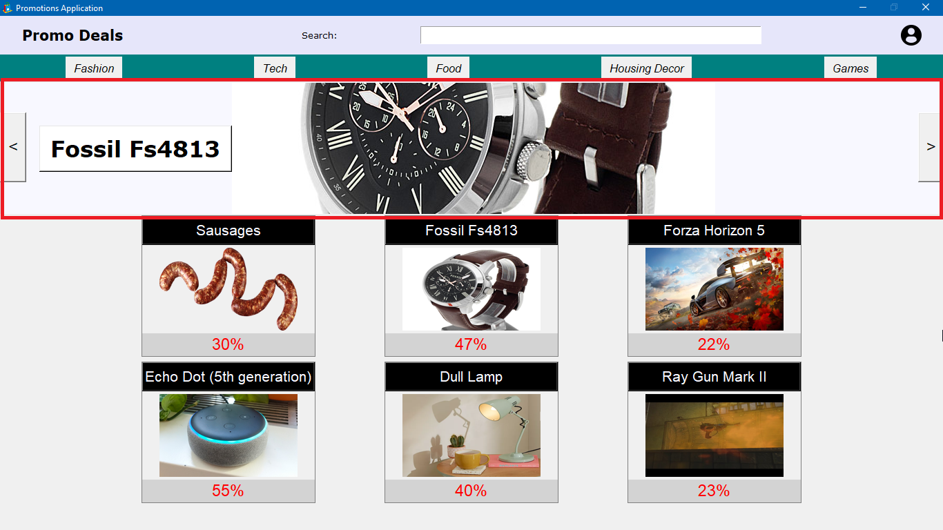
Slider located on app
-
-
Product Window:
-
QR Generator:
Within the Product Page, a unique QR Code for the product source will always be created and saved.
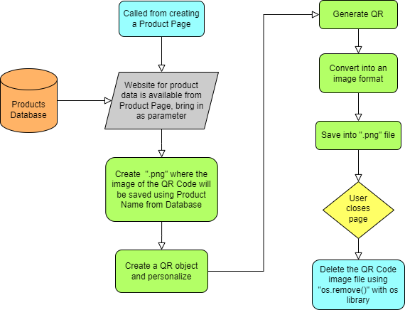
Logic map created prior to coding QR code is not removed after closing the Product Window since this would cause constantly creating the “.png” file on window opening, an unnecessary step. Also, the QR code is styled after its creation.
-
QR Scanner:
To use the QR Code on the same device, a scanner is provided on the same page of the QR Code and transports the user to the website of the product.
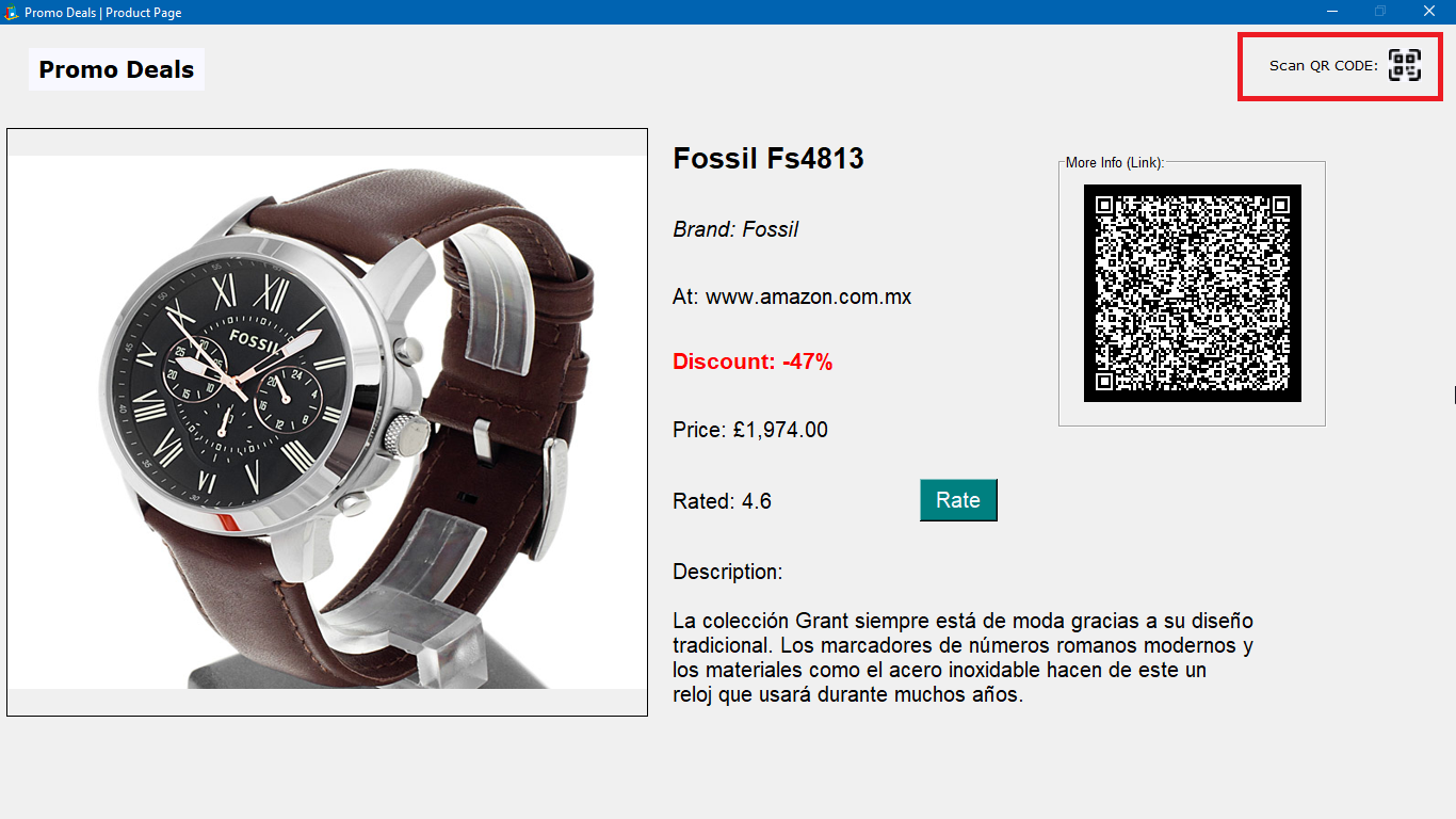
QR scanner located on app
-
-
Rating Window:
This window is useful for users to add their own reflections on products to guide further clients. It is also a method to track user interactions on the application as they are saved to the Database.

Ratings window when openned (Ideally this Window would contain a styled canvas graphic which currently does not appear on the general use of the program due to errors. Although, it was developed for the intention and can be viewed by running the “ratings.py” file on its own.)
The outline of the canvas bar will always be created first, activated on entering text to the Entry widget. It works based on conditionals in the following order:
-
Empty: “Enter a rating”
-
Not a Number: “0.0 – 5.0”

Ratings Window Result -
Number not within 0.0 and 5.0: “Out of Range”

Ratings Window Result -
Correct number: display the bar
-
Under 1: bar is red

Ratings Window Result -
Under 2.5: bar is orange-red

Ratings Window Result -
Under 4: bar is deep sky-blue

Ratings Window Result -
Under 5: bar is spring-green

Ratings Window Result -
Equal to 5: bar is gold

Ratings Window Result
-
-
-
-
Overall System Diagrams

System Flowchart 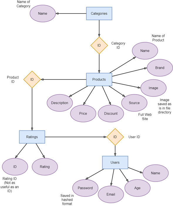
Database ER Diagram
-
- Testing
Errors within codes tend to occupy two categories, syntax errors (incorrect language) and logical error (returning wrong results). Most tests that failed were retested for further errors. Generally, the first rounds of test were for fixing logical errors and second rounds were for syntax errors within the logic.
Although some tests were still left unresolved and others lacked the goals of flexibility, most resolutions imply made no difference for the user of the program in aesthetic or functionality.
The following table provides some main tests that affected the development of the application:
Test Expected Output Actual Output Changes Made Failed Outputs Result Maximum products in Category Window 10 products on Window An error occurred while opening the database: Incorrect number of bindings supplied. The current statement includes 1, and there are 2 supplied. Also, slider not on main page. - Locate SQLite query and execution.
- Query receiving product IDs.
- Viewed of IDs.
- Printed the value “i” and pinpointed problem.
- Program reading a 2-character string as 2 different bindings.
Fix: Tuple format
Success
Save the password in modify while hidden. Save in variable and show ‘*’ while saving actual password. Asterisk saved rather than password. Refer to old password
Problems:
- If password is just asterisks.
- Password data needs updating with entry.
Solution 1:
Save a modified password while not hidden.
Solution 2:
Permanently unhidden.
Solution 2 Failed
Personalized price number. ‘.00’ for last 3 characters, numerical commas. Correct “.00”
Concatenating various characters at a time created logical errors
- Double dot error in sequencing and selection.
- Added final characters to string.
Just commas when testing higher numbers. Failed
Price higher numbers. Styled price. A comma at start of string. Added a condition. Success
Scan QR. Read the data of source. Open in browser with “webbrowser” module. No detected QR. Problem: Black and white color scheme
Solved with pillow
Error: TypeError: startfile: filepath should be string, bytes, or os.PathLike, not tuple Failed
Slider to Product Window. Open Product Window. Works on first call and then opens wrong product pages. Follows same ID as one that calls the slider GUI. Success
Empty search bar. Delete the results. Used while loop, infinite and broke the program. Replaced by conditional testing length equals 0.
Temporarily worked [57]. Although functionality stopped working.
Functionality fixed but results not deleted. Failed
Resizing images. Complete visibility in product list. Resizing frame only crops. Resized using the pillow library. Success
Scrollbar Ratings. Scrollbar range 0.0 up to 5.0 read numerical data. Text widget of 51 numbers. Blank after the final value. Tried modifying loop and indexes.
Could not extract value and we did not cover scrollbars in module.
Change of rating window plan. Failed
Track current signed in. A global variable. Modifying variable is hard with parameters and separate files. Created a text file containing variable. Success
Another effective method which would have been useful for analyzing Database and program scalability would have been to set up a series of tests on program functionalities starting with a low amount of product data in the Database and progressing up to higher amount of data while testing for errors or exponential runtime incompetence.
- Results
Clarity, simplicity, and effective filtering, the objectives of the Promo Deals application, were reached by creating clear plans to singular parts of the program my means of logic brainstorming and flowcharts prior to their development. Even though these plans were not always kept, they provided a space to expand and mold a creative and complex system to guide the user and acquire data correctly.
How accurate were these objectives met:
- Efficient Filtering: Despite some graphical errors in elements such as the search bar and ratings window, the user profile system is filtered to defend the Database form duplicated data, restrain users under the age of 18 from accessing the products and features of the application, and saving user passwords in a hashed format for security.
- Clarity: The application is spread out into different windows which highlight products based on what users are searching for and linking them to main product windows for users to access needed information at any given time.
- Visual Simplicity: Graphic design of the application was made to mimic a simple website format with content on pages organized and spread out in grid formats.
- Video
- Knowledge, Skills and Behaviours
Arduino Hardware
Arduino Software
Arduino Language (C++)
Debugging
Sensors and Actuators
Design for Aesthetics
Project Management
Prototyping
Wiring
Debugging and Testing
Logical Approach
Problem Solving
Detail Oriented
Team Player
- Project Objectives
In my second semester at university, I was tasked to work in a team environment to create a waste segregating smart bin. Designed for urban environments, this bin used sensors, actuators, and a microcontroller to separate wet and dry items into individual waste compartments and informed the user of the classification and when emptying is needed.
The project is an engineering approach to making recycling a simple task.
From the project description, the bin needs to detect if an item placed on a top tray is wet. This tray will have to sort the rubbish into the correct bin compartment. For further user visual information, the sorting results should be shown on a screen, and the fullness of the bin indicated by three lights, one for under 50%, two for under 90%, or all three when full.
- Design
Starting the project, a Gantt chart was created as a plan of design development.
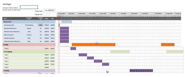
Gantt Chart However, these objectives were poorly followed and the process over time developed accordingly as shown below.
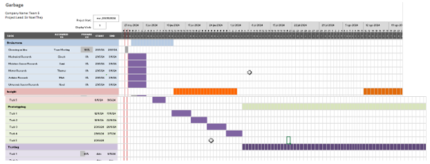
Realistic progress displayed as a Gantt Chart -
Mechanism
Our design process began with a brainstorming session to create ideas for the disposal method. This required a tray according to the brief. Once each method was discussed as a group, a vote by the members determined the final mechanism for the tray. This concept decision took into consideration the build simplicity and time, the components given for the assignment, and the focus of the bin on functionality as an urban tool with a possibly limited amount of operating space.
Results Discussion
The results from this brainstorm are in the following Table along with their corresponding votes. The chosen concept according to votes is highlighted in green.
Categories Concepts Drawing Votes Rotating Base 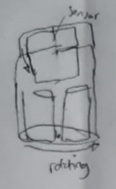
1 Filter 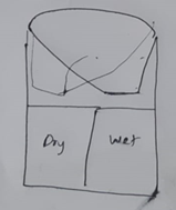
2 Lid Tilting 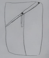
3
Sliding and Pushing 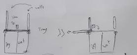
0 Tubes / Pipes Filter / Separator 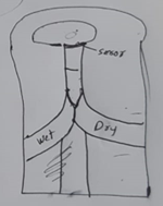
0 Suction 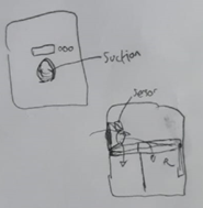
1 Rotating or Pulling 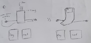
1 Other Pistons 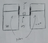
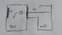
0 Rails 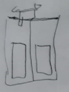
2 Claw 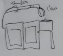
0 Heater 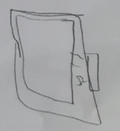
0 -
Logic
I was the main team member responsible for the programming side of the project. Arduino programming is based on Inputs and Outputs and how they can logically depend on each other for a specific task.
Sensors:
- An Ultrasonic Sensor to measure how deep the rubbish level is from being full.
- Another Ultrasonic Sensor to detect if anything is on the tray.
- A Rain Sensor to return the wetness level of the rubbish.
Actuators:
- Six LEDs to indicate how full the bin is. (3 LEDs each bin section)
- An LCD display to notify the user of the section the rubbish was assigned to.
- A Servo sg90 motor to rotate the bin lid.
Although there are additional inputs such as a constant value of 15cm as the maximum depth of the bin, most of the code was based around sensor results. A flowchart I created of the program is shown below.
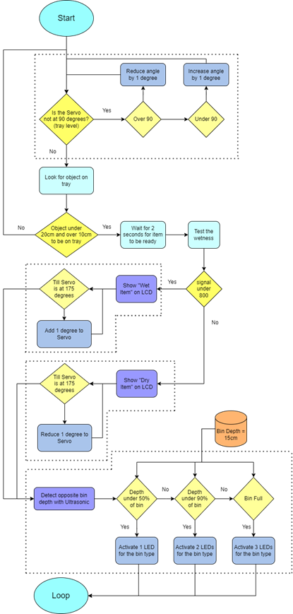
Flowchart Results Discussion
Firstly, the program was built as a single functioned system, but after complexities in logical errors, it became clear that appropriate division of the functions needed to be made. The diagram below divides the code into four main levels: the entire code, the functions, subfunctions, and the related components. A redevelopment progressing from lowest to highest of these levels made both the coding and wiring a smoother process.
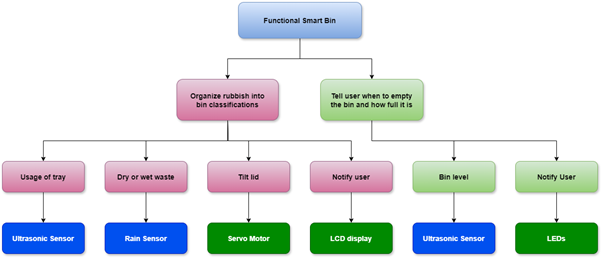
System Breakdown Other than this, most changes in the original code were because of component pins in the electrical system, but functionality remained identical.
An early misunderstanding of the design details meant a major adaptation late in the program development was needed. The ultrasonics had both been used as bin depth detectors, one per bin, and the moisture sensor constantly updated the servo motor despite having no objects on the bin tray. Most of the electronics needed no changes, but the ultrasonics, placed at the rims of the bin, were modified for one above the bin for tray detection and the second on the inferior of the tilting tray. It could then detect a bin depth as it faced the section the tray tilted against.
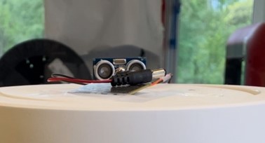
Tray detecting ultrasonic sensor The code was modified so that the rain sensor, LCD, and depth detection would only operate if there was an item between 10 – 20 cm from the surface ultrasonic. This range covers the rain sensor. The flowchart was updated from an older model (below) to the present one.
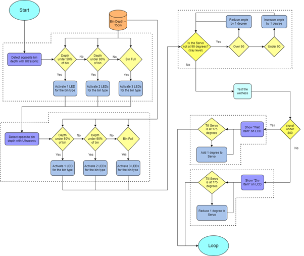
Flowchart before changes -
Electrical Assembly and Simulation
A simulation would have made the process of wiring much quicker and prevented errors. However, the wiring was made physically alongside the Arduino logic. Breadboards were used mainly as power sources and grounds for all components using their power rails connected to the 5V and GND on the Arduino. Each LED used a 220Ω resistor since they were independently connected for having a unique digital pin.
Results Discussion
One of the major problems that occurred and backlogged the design progress was pin layouts on the Arduino board. As components were added and tested on the physical Arduino, 14 digital pins were being consumed by only a portion of the needed components.
- Servo Motor: 1 pin
- Ultrasonics: 4 pins
- LEDs: 6 pins
- LCD: 6 pins
Giving a total of 17 pins for all the components to work on one board.
The first change I made for providing for vacating pins was to rewire and program the ultrasonic sensors using analogue pins.
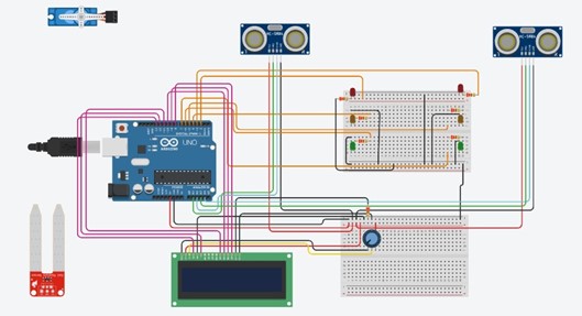
First attempted simulation on Tinker CAD This was possible, but as shown above, it still lacked 1 pin. This is because digital pins 0 and 1 are TX and RX pins used to send signals when information is received or transmitted to the Arduino. This leaves 2 pins less than the original estimated value of 14.
The next modification to the pin layout was to reduce the LCD pins. Being the highest consumer of pins as a single component, a 16x2 LCD cannot use less than 6 pins on its own, but I discovered I2C units made for LCD displays approach communicating data using just a 5V and Ground plus a data pin (SDA) and a pin to clock data (SCL) to the display. Both these pins use analogue A4 and A5 linked as an address. So, with ultrasonics as digital, the full circuit could be wired on a single board and the potentiometer could be removed as I2Cs have one built in.
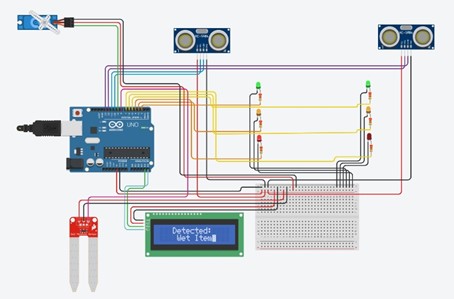
Final wiring simulation on Tinker CAD The final Arduino pin layout is as follows:
Pin Component 5V Breadboard positive terminal GND Breadboard negative terminal A0 Rain Sensor Input A4 LCD SDA pin A5 LCD SCL pin Digital 2 Green LED Digital 3 Yellow LED Digital 4 Red LED Digital 5 Green LED Digital 6 Yellow LED Digital 7 Red LED Digital 8 Rain Sensor Power Pin Digital 9 Servo Motor Digital 10 Ultrasonic Trigger Digital 11 Ultrasonic Echo Digital 12 Ultrasonic Trigger Digital 13 Ultrasonic Echo Electrical Circuit Simulation Schematic:
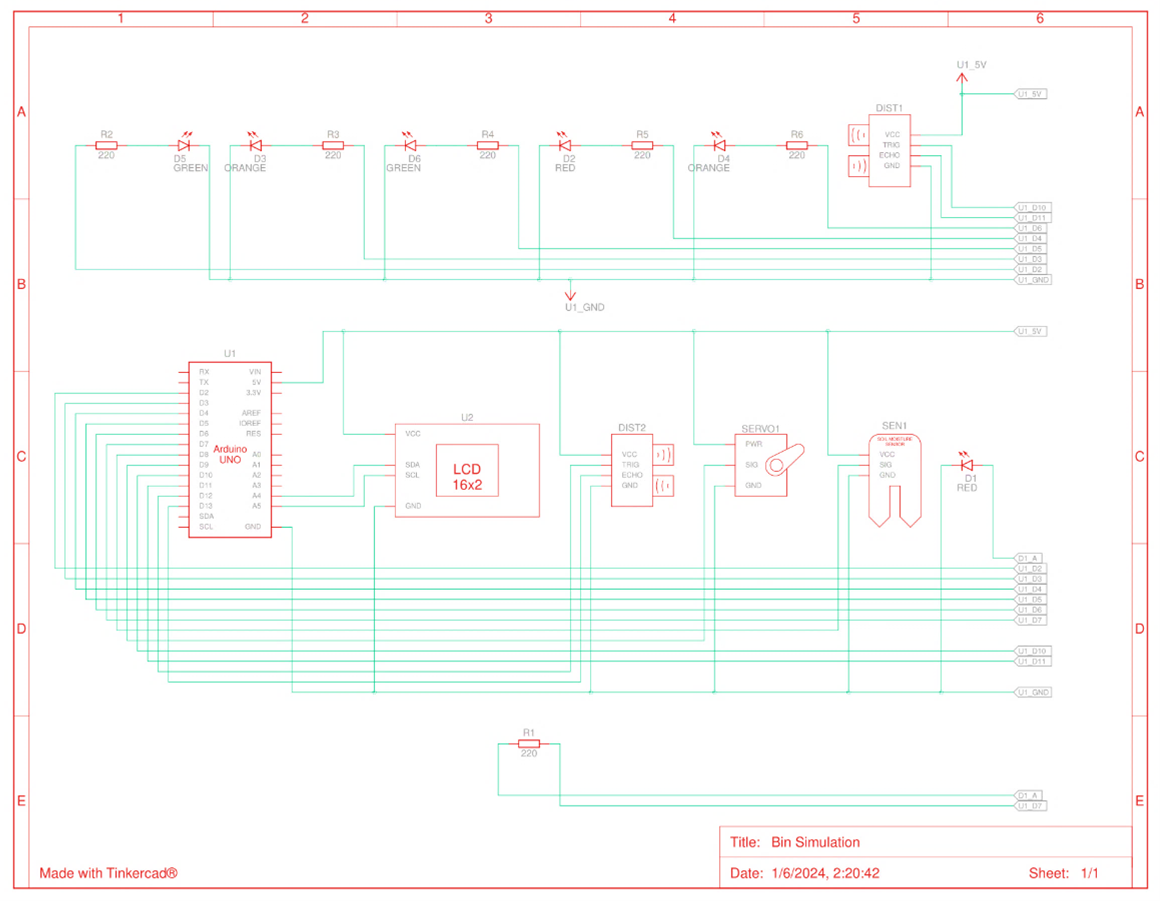
Smart bin schemtic circuit simulation -
Full Assembly and Construction
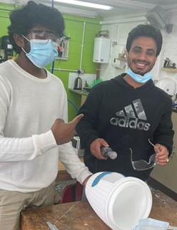
The bin was bought in Lidl. Since it already had a tilting lid, it was chosen and could be adapted to the mechanism design. Parts were made and sections cut to adapt the bin. The following images show these modifications:
Gap in the frontal area of the bin for the fit of a box 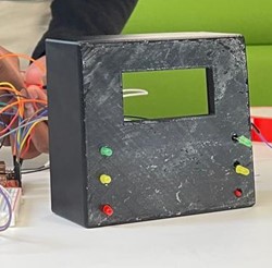
3D printed box for holding the LEDs and LCD on the side of the bin and the Arduino and possibly breadboards on its inside 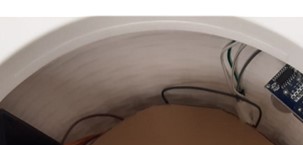
Removal of tray lip so that the lid can tilt both ways 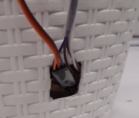
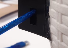
Opening at the base for the wires of external components to reach the Arduino board and other electronic components 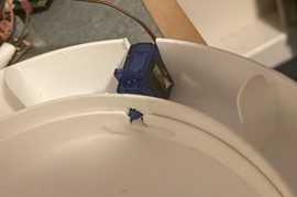
Section in the top border was cut out to fit the Servo Motor where it could form part of the tilting axis of the lid As the circuit was built outside of the box, most wires were held with tape to be identifiable with components, easily accessible for reconnections if loose, and to hold together while incorporating into the bin.
Results Discussion
As discussed in the Logic section, the ultrasonics changed location because of their functionality. The following images show the ultrasonics on the rims before being changed.
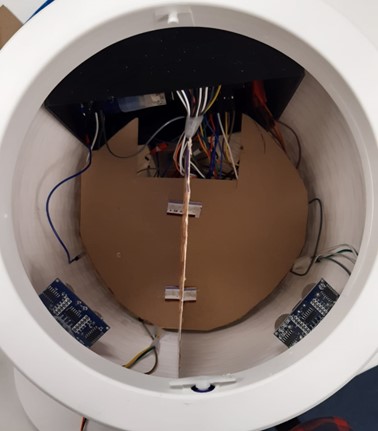
Both ultrasonics at rims of bin sections 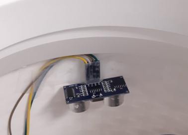
Single Ultrasonic at rim, attachment
-
- System Results
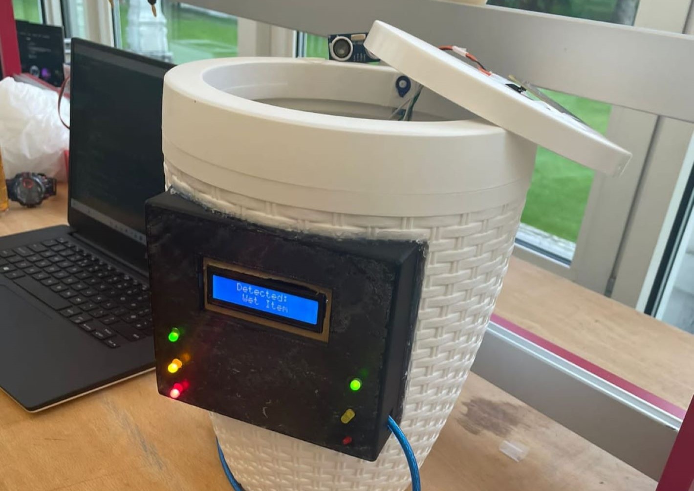
Although the logic and wiring were successful in simulation and before incorporation into the bin, the confined space made disconnections difficult to resolve. Problems with the LEDs having loose connections became common. Especially with the right yellow LED in the image below.
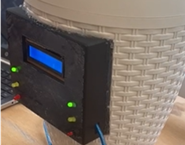
Photo from testing the LEDs The main result error was the internal ultrasonic sensor. When assembled, results on the Serial monitor of the Arduino showed that this component was returning 0.0cm as a distance for most loops and occasionally return a logically incorrect value for the deepness of the bin. The error was resolved as an issue with the supply cable being short and becoming loose on the breadboard at the base of the bin.
The following is a table of each component and its faults (if any) including their results:
Component Fault Solution Rain Sensor No Ultrasonic Sensor 1 No Ultrasonic Sensor 2 Yes
Faulty or no results recieved.
Yes
Extended the Vcc cable to avoid it becoming loose from the breadboard supply line.
Servo sg90 Yes
Stress from trying to over rotate the possible with the lid.
Yes
Reduced by 5 degrees the arc of rotation to each side.
LEDs Yes
Disconnections and no results.
Mostly
Most LEDs were fixed with reconnection except for one.
LCD Display Yes
Not fitting to the box size printed.
Yes
A border made from cardboard was used to fill the gap around the screen and hold it in place.
Final tests of the full bin functionality:
- Final Reflections
As an automated recycling bin for urban use, the bin fulfilled the following:
- Small and portable for spaces like offices and inside homes.
- Accurately detects its use and classifies rubbish into bins adequately.
- A functional simulation for detecting and displaying when the bin compartments need to be emptied.
For further development of the prototype, I would have organized the wiring with more consideration to cleanness and the physical bin size to avoid current errors such as the internal ultrasonic and the LED reconnections; in addition, space efficiency within the bin and robustness would make it a more usable product.
- Knowledge, Skills and Behaviours
3D CAD
BOM
Assembly Instruction Files
2D Drawing
SolidWorks Assembly
Isometric Drawing
SolidWorks 3D CAD
BS8888 Technical Drawing
Reading Technical Drawings
Time Management
- Project Objectives
One of my first projects in university was to digitally Manufacture and create an assembly pack for an angle poise lamp. Since it was for our first semester, this project was intended to show us how to read engineering drawings, use the SolidWorks software, and create the basic documentation which will support all future design projects.
- Provided
2D drawings of some of the major lamp components were provided. We had to replicate these into the CAD software before assembly.
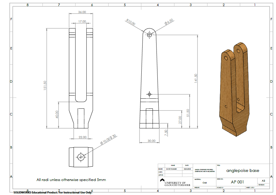
Anglepoise Base 2D Drawing 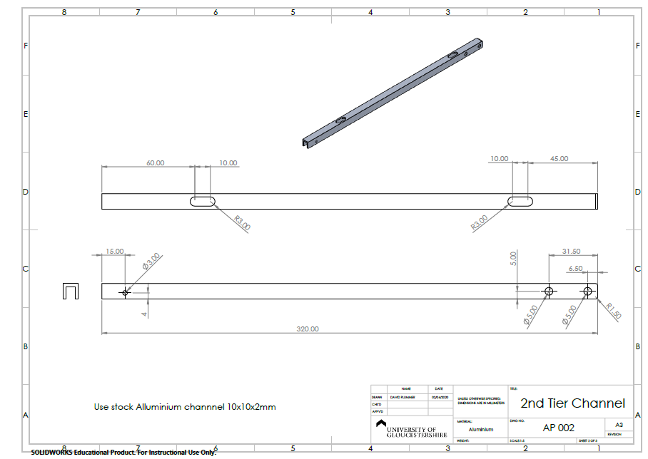
2nd Tier Channel 2D Drawing 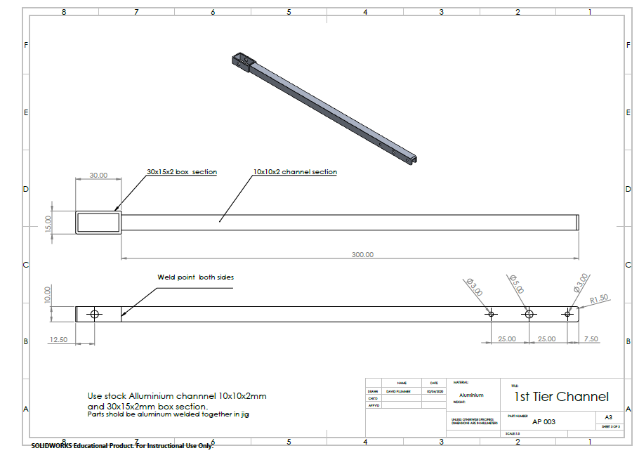
1st Tier Channel 2D Drawing 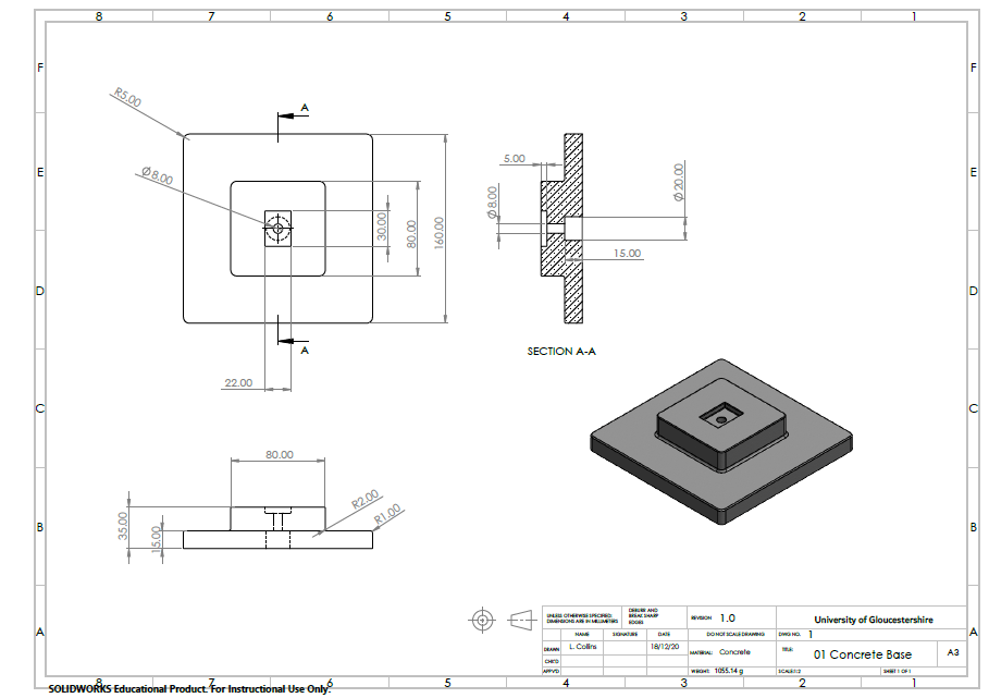
Concrete Base 2D Drawing 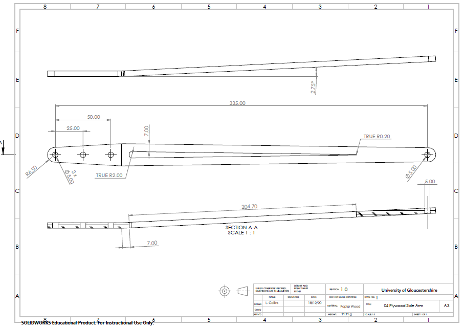
Plywood Side Arm 2D Drawing 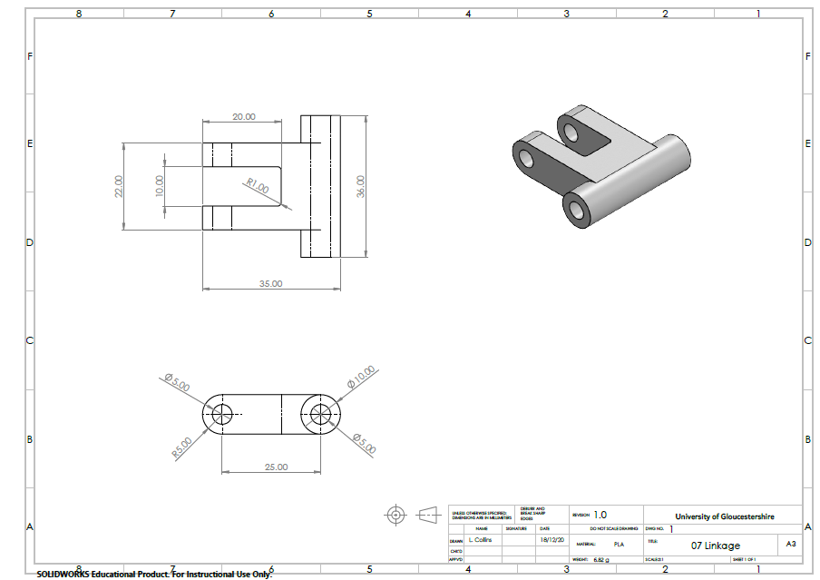
Linkage 2D Drawing 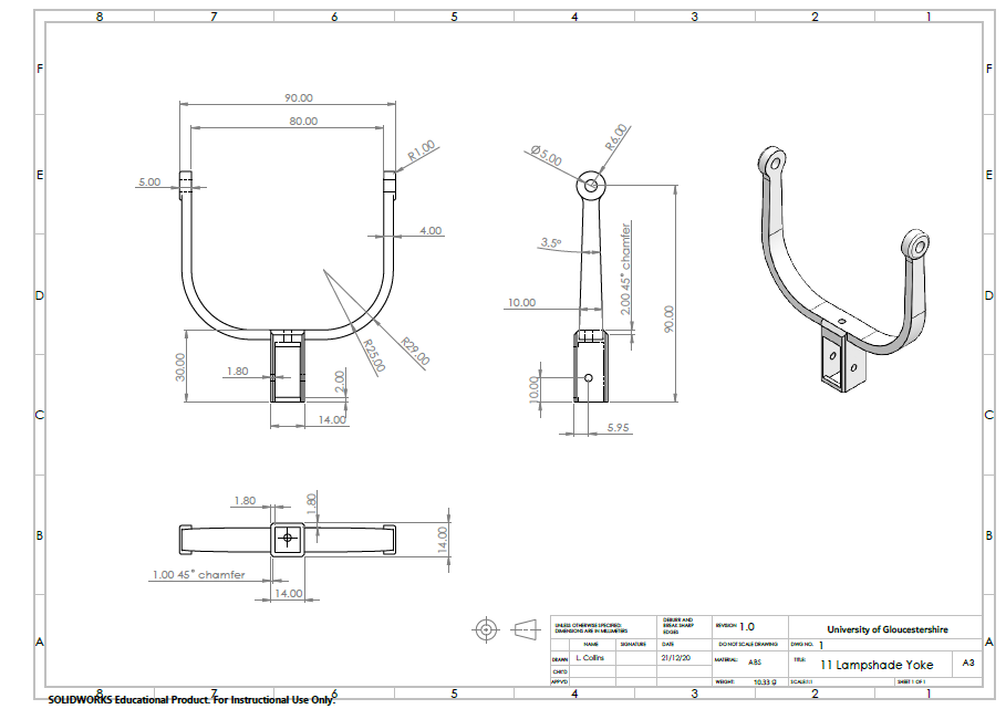
Lampshade Yoke 2D Drawing 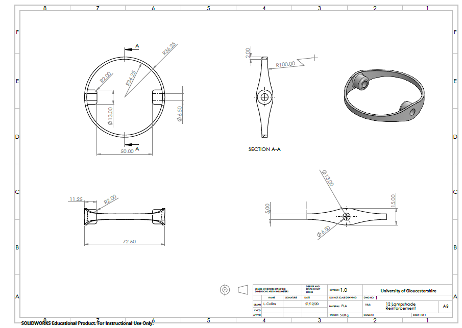
Lampshade Reinforcement 2D Drawing 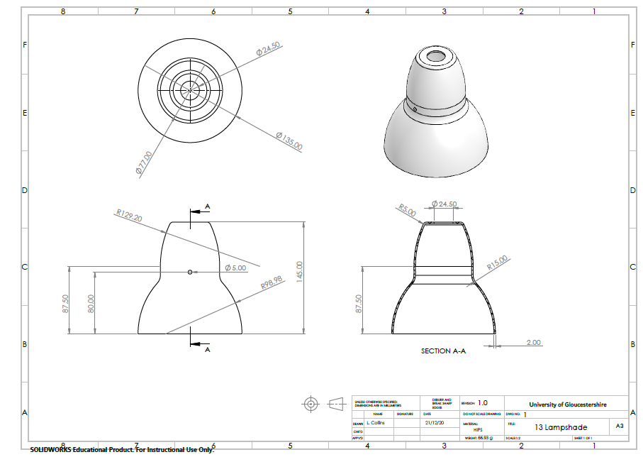
Lampshade 2D Drawing - Results
2D to 3D copied components:
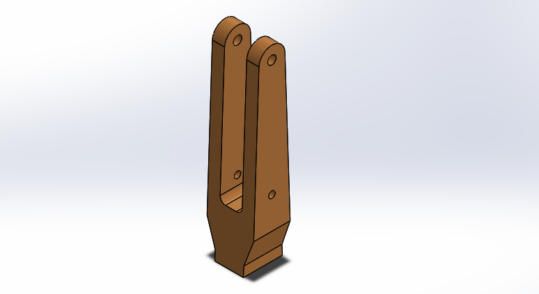
Anglepoise Base 3D CAD Model 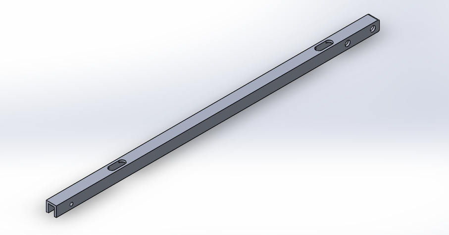
2nd Tier Channel 3D CAD Model 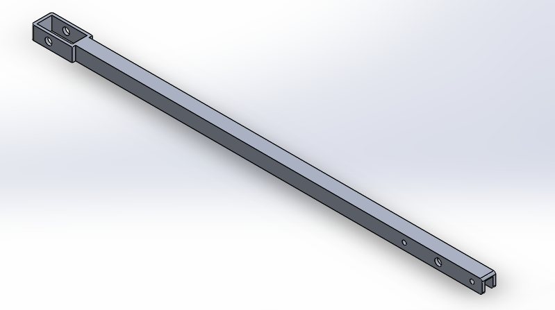
1st Tier Channel 3D CAD Model 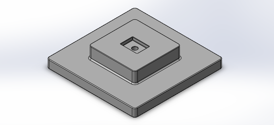
Concrete Base 3D CAD Model 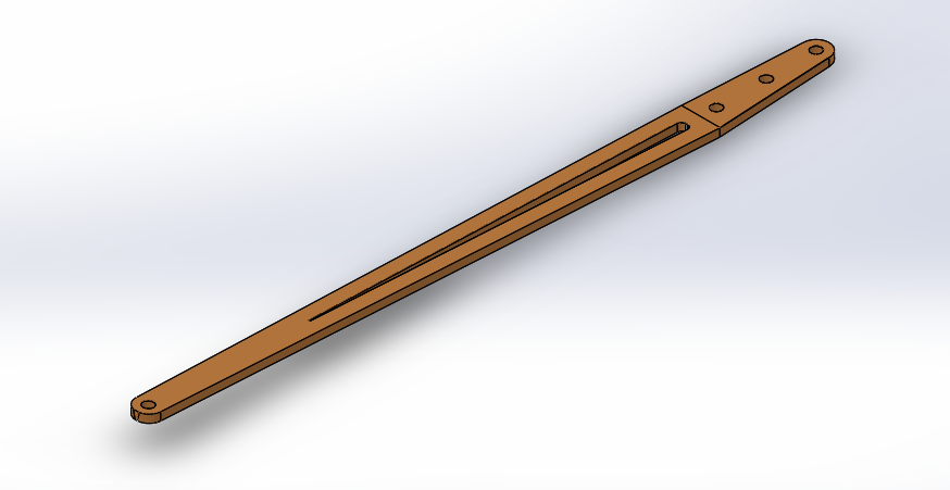
Plywood Side Arm 3D CAD Model 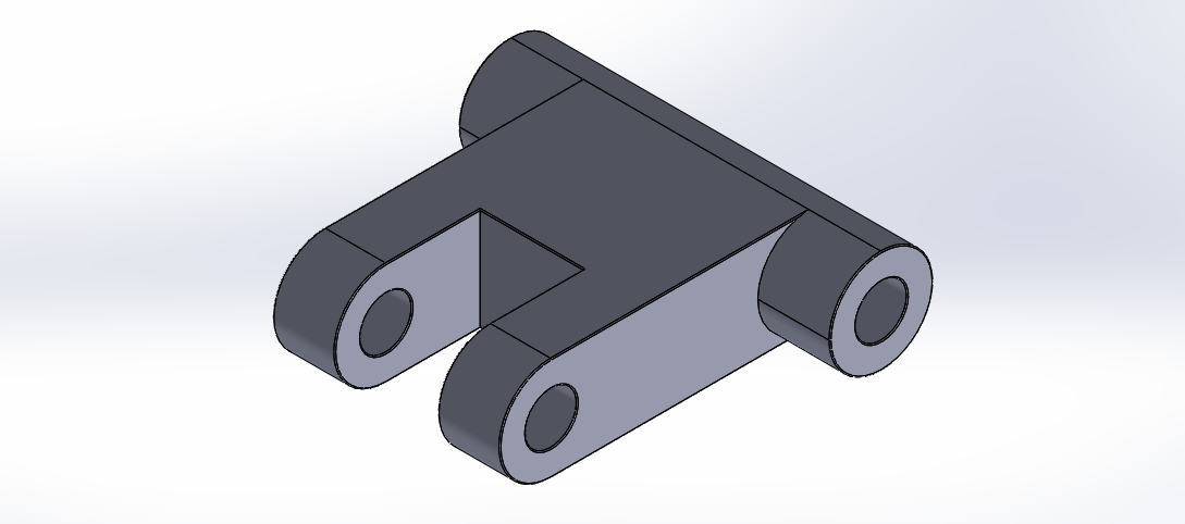
Linkage 3D CAD Model 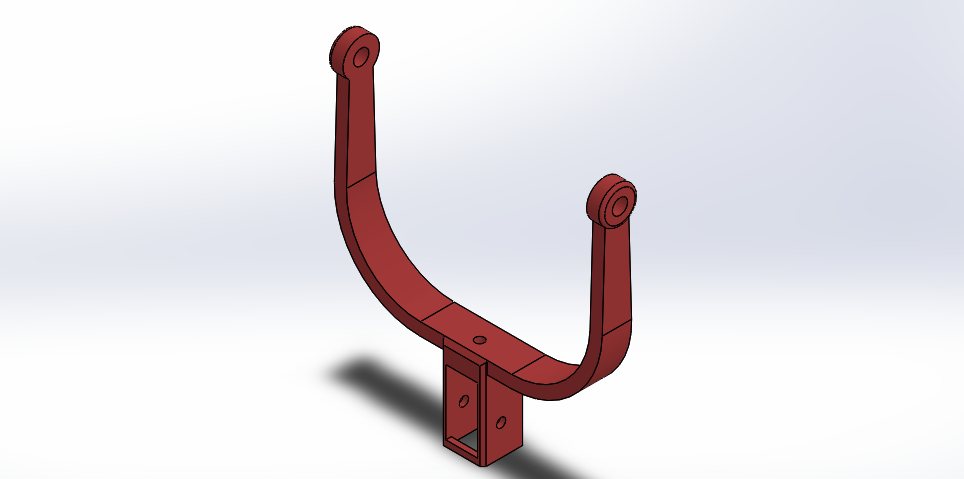
Lampshade Yoke 3D CAD Model 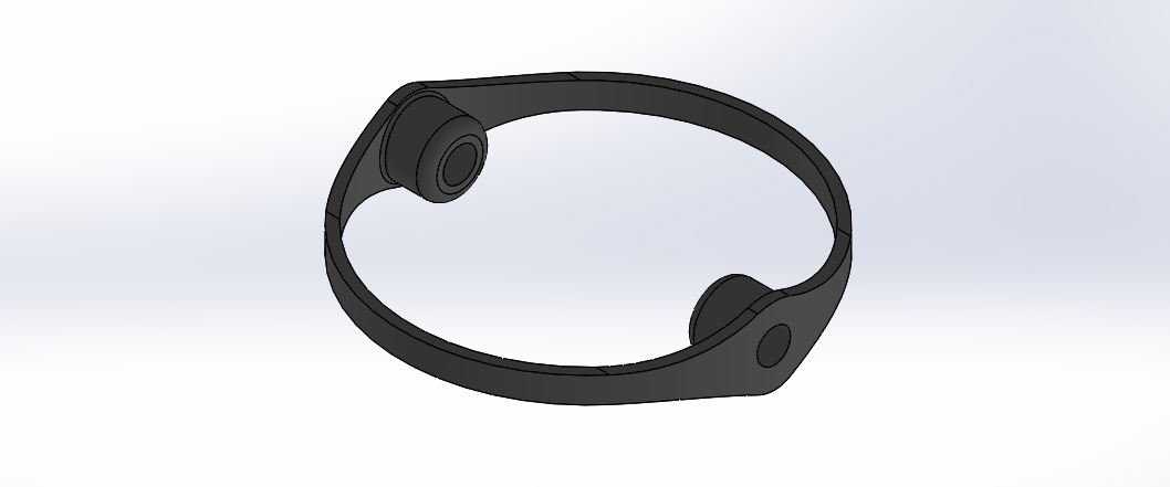
Lampshade Reinforcement 3D CAD Model 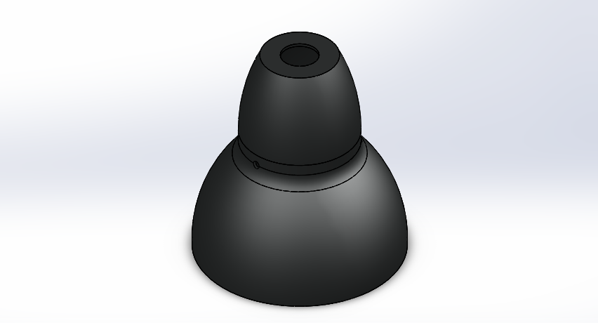
Lampshade 3D CAD Model SolidWorks assembly:
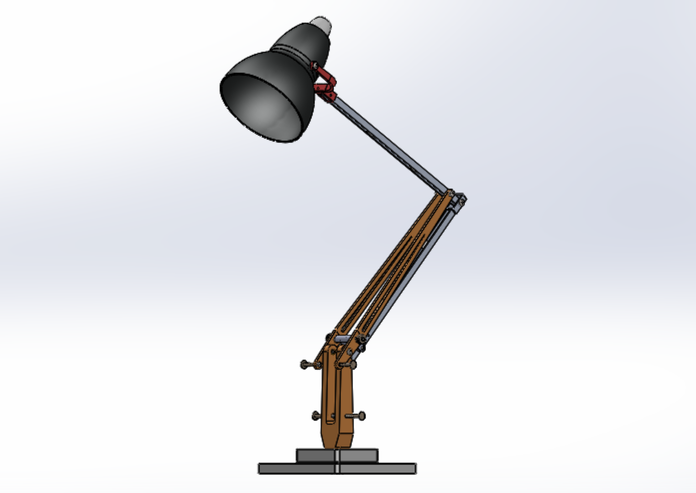
Lampshade 3D CAD Model Assembly Instructions File:
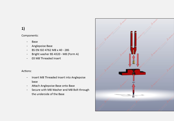
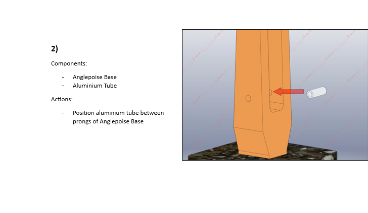
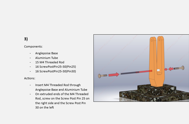
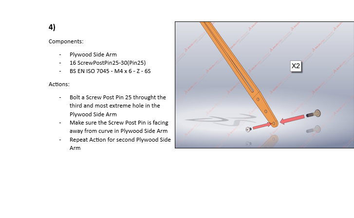
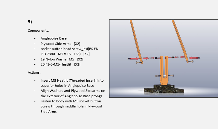
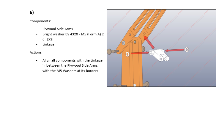
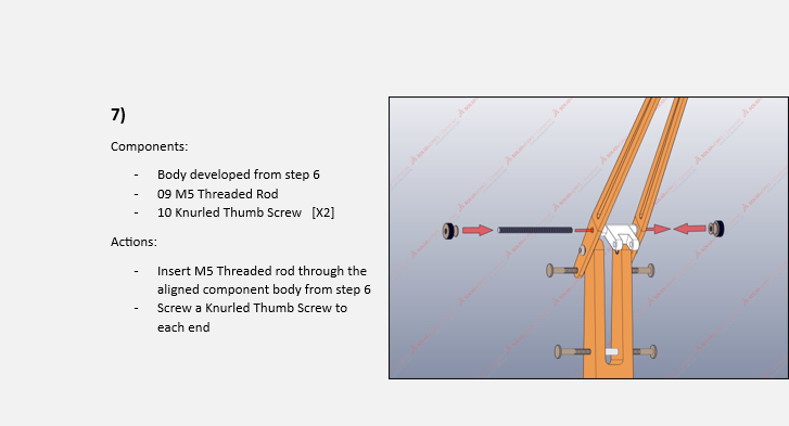
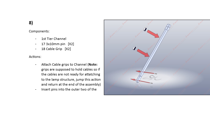
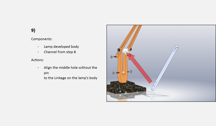
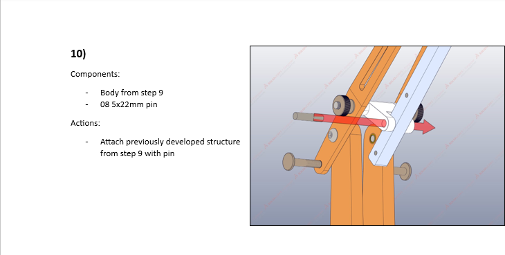
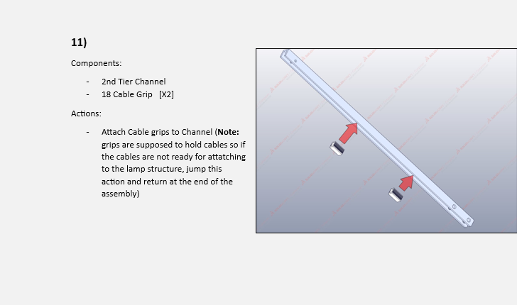
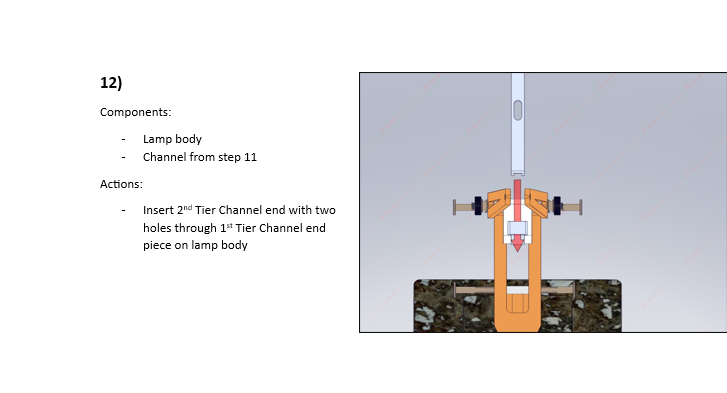
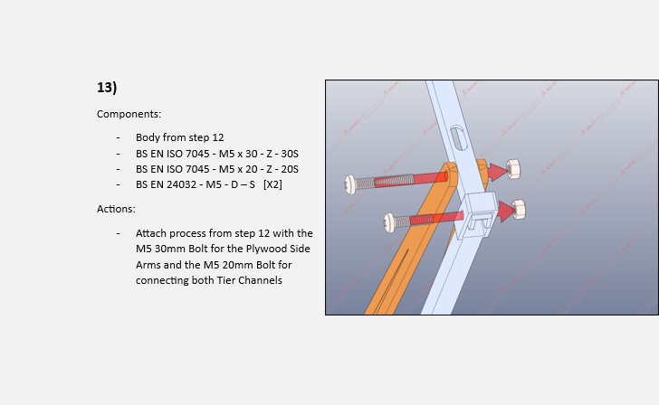
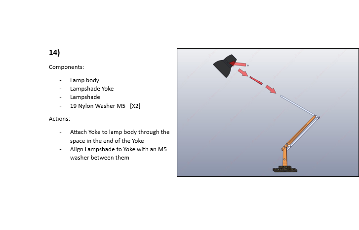
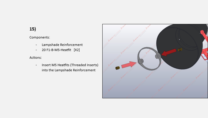
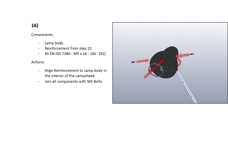
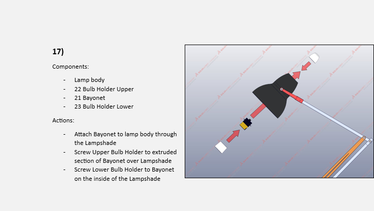

Exploded drawing:
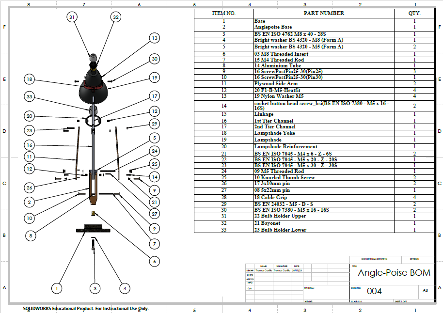
Anglepoise Lamp Exploded CAD Model BOM:
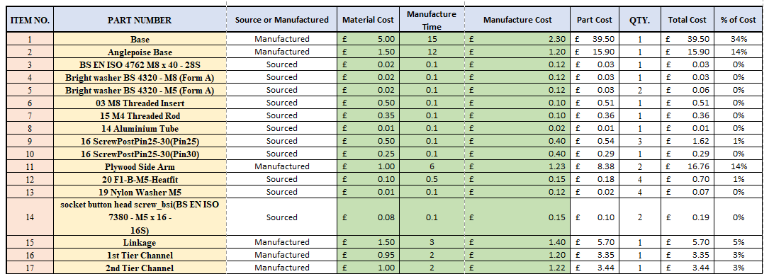
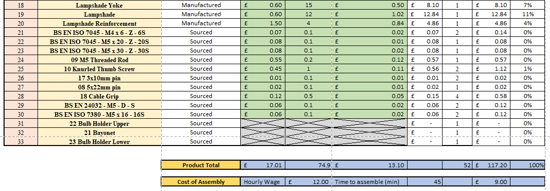

Anglepoise Lamp Bill of Materials - Discussion
This assignment developed essential knowledge and skills for supporting innovation and product development for many future projects. Alongside this, this project was only one of the 4 hand-ins for the module. The others included a workshop part to manufacture, manufacturing processes research, and a job search and description. These 4 hand-ins made time management an important part of the process.
Contact Me
- Spencer Johnson
